
Chapter objective: Attachment compatibility is often treated as a question of whether an attachment can be physically connected to a machine. That is only the first layer. A professionally verified match requires the carrier and attachment to agree across several independent systems: mounting geometry, hydraulic flow, hydraulic pressure, electrical controls, attachment mass, carrier lifting capacity, stability, hose routing, coupler type and the intended operating environment. A bucket may pin onto an excavator correctly yet still...
Why compatibility is a system, not a single measurement
Attachment compatibility is often treated as a question of whether an attachment can be physically connected to a machine. That is only the first layer. A professionally verified match requires the carrier and attachment to agree across several independent systems: mounting geometry, hydraulic flow, hydraulic pressure, electrical controls, attachment mass, carrier lifting capacity, stability, hose routing, coupler type and the intended operating environment. A bucket may pin onto an excavator correctly yet still exceed the machine's recommended mass. A mower may attach to a skid steer plate but demand more hydraulic power than the auxiliary circuit can provide. A grapple may function at ground level but reduce stability when carried at full reach. Compatibility therefore means that the complete machine-and-attachment combination remains secure, controllable and within the published limits throughout the planned work cycle.
The safest professional habit is to separate the decision into documented checks rather than relying on visual similarity or previous experience with a different model. Machines that look almost identical can use different coupler widths, pin diameters, hydraulic settings or software controls. Attachments sold under the same product name may also be available in multiple mounting and hydraulic configurations. Treat every new pairing as a new engineering check, even when the equipment appears familiar.
The five compatibility domains
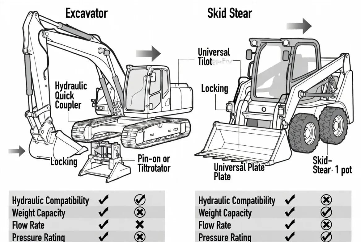
A useful field framework divides compatibility into five domains. Mechanical compatibility confirms that the attachment interface, pin dimensions, latch geometry and locking method are correct. Hydraulic compatibility checks required flow, pressure, return configuration, case drain and coupler size. Structural compatibility confirms that the attachment weight, working load and dynamic forces remain within the carrier's limits. Electrical compatibility covers control harnesses, solenoids, sensors and machine software. Operational compatibility considers the task itself, including reach, visibility, ground conditions, travel, transport and the consequences of a failure.
A match should not be marked as confirmed when one domain is unknown. Instead, use a clear status such as “Compatibility Not Verified” or “Hydraulic Check Required.” This protects operators from interpreting partial information as approval. When an adapter is needed, the adapter becomes part of the system and its weight, strength, lock condition and effect on geometry must be included in the assessment. The final answer is not simply yes or no; it should explain the conditions under which the attachment can be used and the checks that remain the operator's responsibility.
Mechanical interface verification
Begin with the manufacturer drawing or approved fitment chart. For excavators, record the pin diameter, pin-centre distance, ear spacing, coupler family, linkage geometry and any model-specific restrictions. For skid steers and compact track loaders, confirm that the quick-attach plate follows the required standard and that the latch pins fully engage the attachment pockets. For loaders, telehandlers and tractors, verify carriage type, hook spacing, locking pins and hydraulic or electrical connections. Never assume that an interface described as “universal” is universal across every machine class, year or region.
Inspect the physical surfaces before connection. Bent ears, worn pin bores, cracked welds, damaged latch pockets or accumulated debris can prevent full engagement even when the nominal dimensions are correct. After coupling, perform both a visual check and a controlled functional check close to the ground. The attachment should seat evenly without abnormal side movement. Lock indicators must show the correct condition, and any secondary retaining device must be installed. If the fit requires force, improvised spacers, welding or unapproved modification, stop and obtain the correct mounting solution.
Hydraulic and electrical verification
Hydraulic attachments must be matched by more than connector size. Record the attachment's minimum and maximum flow, allowable pressure, preferred back-pressure, motor or cylinder type, case-drain requirement and whether the circuit must be one-way or bidirectional. Compare those values with the carrier's actual auxiliary settings, not only its maximum published capability. A machine capable of high flow may need to be electronically limited for a smaller motor. A breaker may require a free-flow return path. A mulcher or planer may require a case drain and specific cooling capacity.
Electrical controls can be equally important. Some attachments use a simple on-off solenoid; others need proportional control, CAN communication, speed sensors or a dedicated control box. Confirm voltage, connector pinout, fuse protection and software support. Do not bridge wires or bypass interlocks to make an attachment operate. If an attachment works only intermittently, investigate the control specification and wiring integrity rather than assuming the hydraulic system is at fault. All hoses and cables should be long enough for the full movement envelope but routed to avoid pinch points, abrasion and hot surfaces.
Weight, capacity and stability
Attachment weight changes the carrier's centre of gravity and consumes part of its available lifting or operating capacity before any payload is added. The effect becomes more significant as the load moves farther from the machine. A heavy grapple, coupler and adapter can substantially reduce the material that may be handled safely. For excavators, use the lifting chart for the actual boom, arm, counterweight, track position and working radius. For skid steers and loaders, consider rated operating capacity, tipping load and the attachment's forward centre of gravity. For telehandlers, use the correct load chart for the carriage and attachment configuration.
Dynamic work also creates forces beyond static weight. Breaking, prying, sweeping, side loading, impact and high-speed travel can transfer loads into pins, booms, lift arms and frames. An attachment may be structurally acceptable for light handling but unsuitable for aggressive demolition. Maintain the carrier in the stable orientation recommended by the manufacturer, use the lowest practical travel position and avoid turning or travelling rapidly with a raised load. If the combination causes poor visibility, unstable steering, excessive rear lift or sluggish lift-arm response, reassess the attachment size and work method.
A disciplined compatibility workflow
Use a repeatable process. First, identify the exact carrier model, serial range and configuration. Second, identify the exact attachment model, mounting version and hydraulic package. Third, collect manufacturer documents for both. Fourth, compare mechanical geometry, hydraulic requirements, electrical controls, weight and capacity. Fifth, document any adapter, hose kit, control kit or setting change. Sixth, inspect the condition of the interface. Seventh, connect and test at low speed in a controlled area. Finally, record the result, limitations, verification date and sources.
This workflow should be completed before the attachment enters production. A verbal assurance from a seller or a previous user is useful background but is not a substitute for documentation. When multiple machines may share the same attachment, create a separate record for each pairing. If a machine is modified, fitted with a different coupler or updated with new control software, review the compatibility record. A professional database should never copy a compatibility statement from one model to another only because the machines have similar operating weights.
Common failure patterns and warning signs
Compatibility problems often reveal themselves through predictable signs: the attachment will not sit squarely; latch pins do not reach the full locked position; hoses become tight at full curl; couplers run hot; hydraulic movement is slow or violent; the attachment stalls repeatedly; the carrier lifts at the rear; warning messages appear; or unusual noise and vibration develop. These are not normal break-in conditions. Stop, lower the attachment safely and investigate. Continuing to operate can convert a small mismatch into structural damage, oil contamination, hose failure or a dropped attachment.
Avoid common shortcuts. Do not select an attachment only by bucket width, carrier tonnage or connector appearance. Do not assume an adapter automatically solves every fitment issue. Do not set the machine to maximum flow “to make it stronger.” Do not exceed a load chart because the machine feels stable during one lift. Do not disable alarms or safety locks. A professional operator is willing to pause work when the system does not behave as expected.
Documentation, labeling and communication
Good compatibility management is visible and easy to use. Attachments should carry a readable identification plate. The job file should include the approved carrier list, hydraulic settings, required adapters, hose routing notes, capacity limitations and inspection requirements. Where several similar attachments are stored together, use durable labels or color coding to prevent incorrect connection. Operators should know where the source documents are stored and how to report a discrepancy.
Record the date of the check and the person or organization that supplied the information. Keep photos of the mounting interface and lock position when useful. If the attachment is transferred to another site or machine, send the compatibility record with it. This is especially important for rented or used attachments, where plates may be missing and previous modifications may not be documented. Clear information reduces setup time, prevents repeated research and supports consistent decisions across shifts.
Field checklist and decision outcome
Before release to work, confirm the exact carrier and attachment identities; approved mounting interface; complete primary and secondary locking; attachment and adapter weight; carrier capacity at the intended radius; hydraulic flow and pressure settings; return and case-drain requirements; hose and cable routing; electrical connector and controls; visibility; transport position; and manufacturer restrictions. Test every function at low speed with the attachment close to the ground.
Use one of five clear outcomes: Confirmed Compatible, Compatible with Adapter, Hydraulic Check Required, Not Compatible or Compatibility Not Verified. Include a short explanation and any operating conditions. The most important rule is simple: uncertainty is not compatibility. When information is missing, keep the attachment out of service until the combination has been verified from authoritative documentation or by a qualified technical source.
Key takeaways
Compatibility is a complete system decision. Physical connection alone is not proof of safe use. Mechanical geometry, hydraulics, electrical controls, weight, capacity and the operating task must all be checked. Verification should be model-specific, documented and repeated after modifications. Adapters and couplers add weight and create additional inspection points. When any essential value is unknown, use a non-confirmed status and obtain the correct information before operation. Manufacturer documentation remains the authoritative source for ratings, approved configurations and operating procedures.
Manufacturer authority: Use the current carrier and attachment manuals, approved fitment charts and service limits as the final source for ratings, settings, inspection criteria and operating procedures.
Get More Expert Guides & Updates
Subscribe for Machinery.org guide updates and product learning content.