
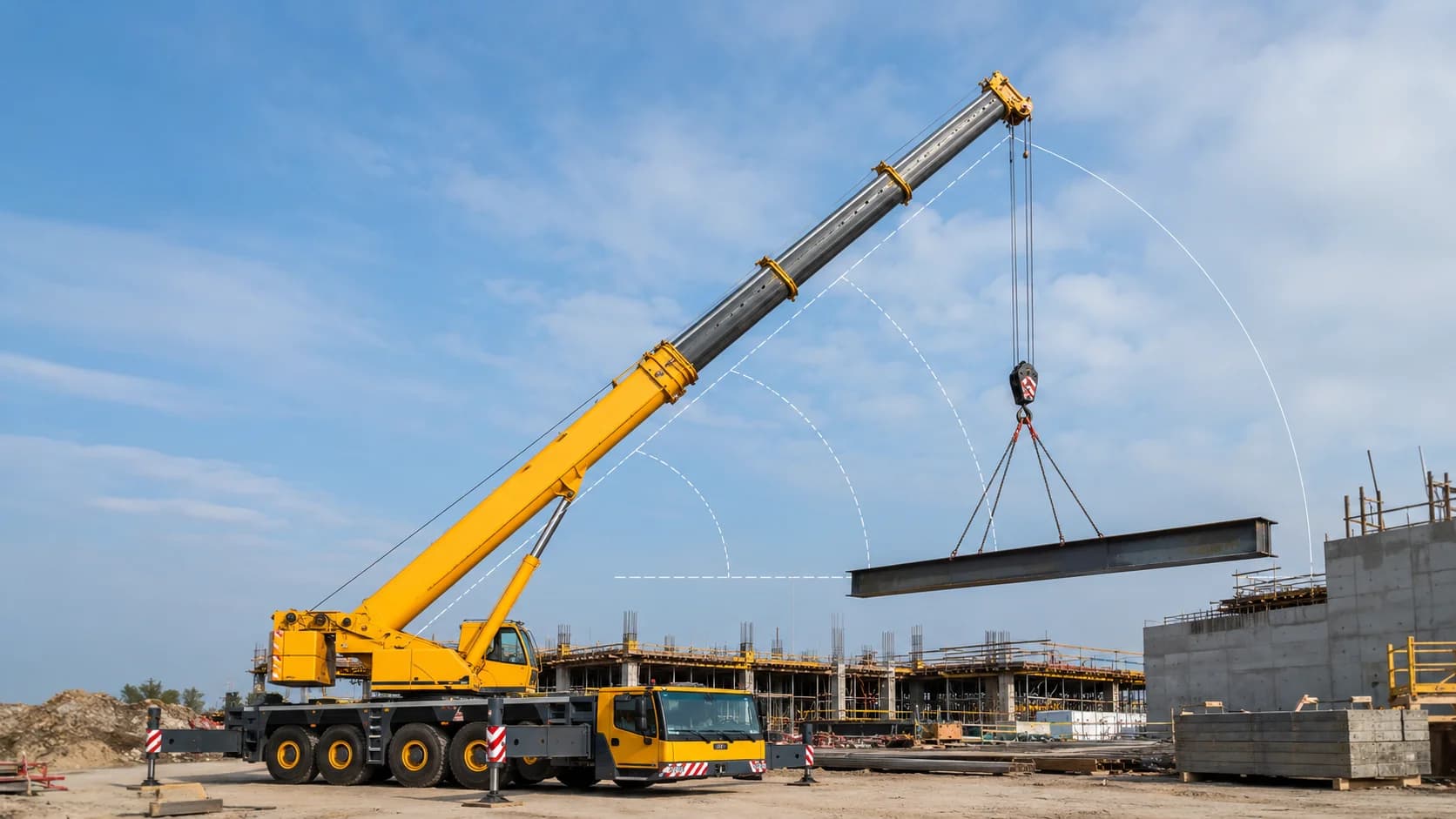
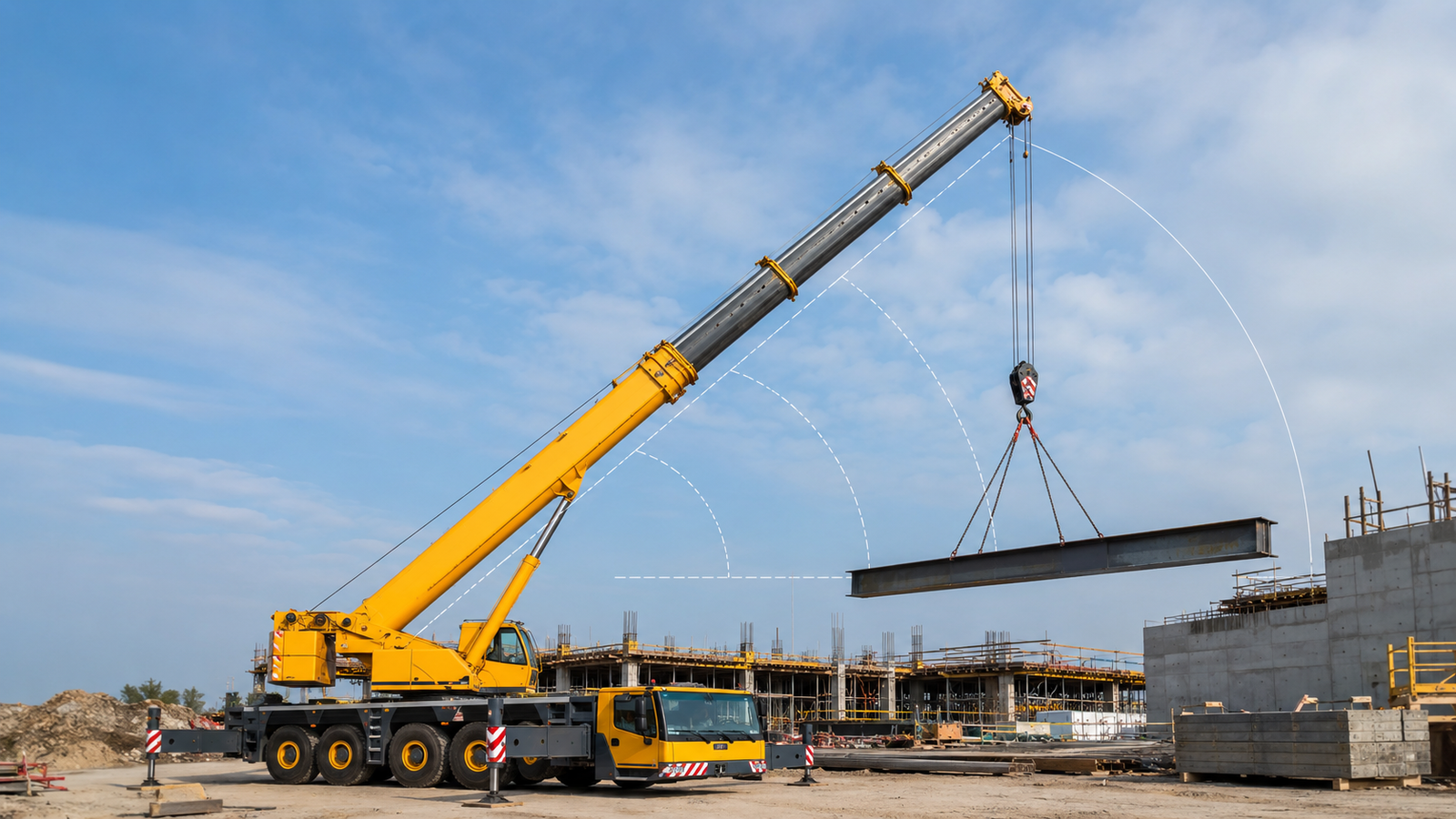
A mobile crane load chart is the operating map that connects crane configuration to allowable lifting capacity. It is not a single maximum-capacity number. The chart changes with working radius, boom length, boom angle, counterweight, outrigger position, reeving, attachments, and sometimes the direction of the lift. A crane advertised as a certain tonnage may be capable of that rating only at a short radius in a particular setup. As the load moves farther from the crane, the overturning moment increases and capacity normally falls. For operators, lift directors, riggers, estimators, and project managers, learning how to read the chart is one of the most important steps in planning a safe lift. This guide explains the logic behind radius, boom length, gross and net capacity, deductions, configuration notes, and the practical checks that should be completed before a hook ever leaves the ground.
Use this guide with the exact manufacturer documentation. Capacities, configuration limits, inspection criteria, and operating procedures vary by crane model and jurisdiction.
What a Mobile Crane Load Chart Actually Tells You
The chart applies only to the crane configuration printed on that page, including the stated counterweight, boom system, outrigger position, tires or supports, and any specified attachment condition. Confirm this point against the exact crane data and the actual field condition before proceeding.
Rated capacity is normally shown at combinations of working radius and boom length, so the operator must locate the correct intersection rather than relying on a headline crane tonnage. Confirm this point against the exact crane data and the actual field condition before proceeding.
Charts may contain structural limits in one area and stability limits in another, and the user should treat every printed value as a maximum under the stated conditions rather than a target to exceed. Confirm this point against the exact crane data and the actual field condition before proceeding.
Footnotes, shaded areas, symbols, and configuration notes can change the meaning of a table value, which is why the complete chart page and notes must be read together. Confirm this point against the exact crane data and the actual field condition before proceeding.
The chart is part of a larger lift-planning process that also includes actual load weight, rigging weight, hook block, line pull, site conditions, boom clearance, and manufacturer instructions. Confirm this point against the exact crane data and the actual field condition before proceeding.
On a congested project, the limiting condition may occur later in the swing or at the set point, so check the complete lift envelope before mobilization.
Understanding Working Radius
Working radius is the horizontal distance from the crane rotation center to the vertical line through the suspended load, not simply the distance from the crane bumper or outrigger pad to the load. Confirm this point against the exact crane data and the actual field condition before proceeding.
Radius can increase during a lift when the boom deflects under load, the load is boomed down, the crane settles, or the operator swings into a less favorable position. Confirm this point against the exact crane data and the actual field condition before proceeding.
A small increase in radius can cause a significant reduction in chart capacity because overturning moment is strongly influenced by how far the load acts from the crane centerline. Confirm this point against the exact crane data and the actual field condition before proceeding.
The planned radius should be based on the worst practical point of the lift, including the pick, swing path, and set location, rather than only the easiest point in the cycle. Confirm this point against the exact crane data and the actual field condition before proceeding.
Accurate site layout helps the crew verify crane position, obstruction clearance, and the true distance to the load before selecting a chart value. Confirm this point against the exact crane data and the actual field condition before proceeding.
Marking the crane center, support locations, load path, and landing area before setup makes the assumptions visible to the entire lifting team.
Boom Length, Boom Angle, and Capacity
Longer boom length is not automatically better because extending the boom adds weight and changes geometry, often reducing the capacity available at a given radius. Confirm this point against the exact crane data and the actual field condition before proceeding.
Boom angle is related to radius but should not be substituted for radius unless the manufacturer chart specifically instructs the user to work from boom angle. Confirm this point against the exact crane data and the actual field condition before proceeding.
Telescopic boom sections may have prescribed extension sequences or modes, and two booms with the same overall length can have different capacities if the extension pattern differs. Confirm this point against the exact crane data and the actual field condition before proceeding.
Jibs, lattice extensions, auxiliary heads, and other attachments can add reach while also creating required deductions or separate load charts that must be used. Confirm this point against the exact crane data and the actual field condition before proceeding.
Boom deflection under load is normal within design limits, but it can increase radius and should be considered when the lift has little capacity margin or tight clearance. Confirm this point against the exact crane data and the actual field condition before proceeding.
When uncertainty remains, conservative planning is more reliable than using every unit of theoretical capacity. Keep usable margin for normal variation in weight, radius, and positioning.
Gross Capacity, Net Capacity, and Deductions
The capacity printed in a chart is commonly a gross rated load, meaning the allowable suspended total may include the hook block, ball, slings, shackles, spreader bars, lifting beams, and other below-the-boom equipment. Confirm this point against the exact crane data and the actual field condition before proceeding.
Net payload is found only after all required deductions have been subtracted from the gross chart capacity, so a lift can be overloaded even when the object itself weighs less than the table value. Confirm this point against the exact crane data and the actual field condition before proceeding.
The weight of unused or stowed attachments may still require a deduction if the manufacturer chart says they influence the crane configuration. Confirm this point against the exact crane data and the actual field condition before proceeding.
Rigging weight should be known or conservatively estimated before finalizing a lift plan, especially for heavy lift beams, multi-leg slings, large shackles, or specialized below-the-hook devices. Confirm this point against the exact crane data and the actual field condition before proceeding.
A good calculation sheet clearly separates load weight, rigging weight, hook or block weight, attachment deductions, gross chart capacity, and the resulting margin. Confirm this point against the exact crane data and the actual field condition before proceeding.
After weather changes, relocation, or a configuration change, reconfirm the condition that controls the lift instead of assuming the earlier setup is still valid.
Outriggers, Tires, Counterweight, and Setup Variables
A crane on fully extended outriggers can have a very different chart from the same crane on partially extended outriggers, on rubber, or with supports configured differently. Confirm this point against the exact crane data and the actual field condition before proceeding.
Some cranes use working-area charts that distinguish lifts over the front, rear, or side because stability and structural behavior change with slew position. Confirm this point against the exact crane data and the actual field condition before proceeding.
Counterweight quantity must match the selected chart exactly; adding or removing counterweight changes both capacity and axle or ground loading. Confirm this point against the exact crane data and the actual field condition before proceeding.
The crane must be level within manufacturer limits because an out-of-level condition can shift the effective radius and reduce stability in a way the chart does not assume. Confirm this point against the exact crane data and the actual field condition before proceeding.
Ground support, outrigger reactions, mats, and pad sizing are not optional details because a perfectly read chart cannot compensate for soil or support failure beneath the crane. Confirm this point against the exact crane data and the actual field condition before proceeding.
A short handover record of configuration, key dimensions, support assumptions, rigging, and restrictions helps prevent the next shift from using an outdated plan.
A Practical Load-Chart Reading Workflow
Start by confirming the exact crane model, boom system, counterweight package, outrigger or tire configuration, reeving arrangement, and whether a jib or auxiliary head is installed. Confirm this point against the exact crane data and the actual field condition before proceeding.
Determine the maximum planned working radius and required boom length from an accurate site layout, then select the matching chart page before looking for a capacity value. Confirm this point against the exact crane data and the actual field condition before proceeding.
Find the table capacity at the selected radius and boom length, read every applicable note, and use the next more conservative radius or length when the chart does not list the exact planned condition. Confirm this point against the exact crane data and the actual field condition before proceeding.
Subtract all required load-handling equipment and attachment deductions to determine net capacity available for the object being lifted. Confirm this point against the exact crane data and the actual field condition before proceeding.
Compare net capacity with verified load weight and keep appropriate planning margin so normal variations such as boom deflection, positioning tolerance, and minor weight uncertainty do not create an overload. Confirm this point against the exact crane data and the actual field condition before proceeding.
For example, a lift can change when the crane must be positioned farther away than planned. Recalculate the working condition rather than treating the extra radius as insignificant.
Field Planning Checklist
Before the lift begins, convert the planning discussion into a short field checklist. A checklist does not replace judgment; it makes sure the agreed assumptions are visible and repeatable. The following items should be adapted to the exact crane, manufacturer instructions, project lift plan, and local requirements:
- Verify exact crane model and serial-specific chart where required.
- Confirm counterweight and outrigger configuration.
- Measure or calculate worst-case working radius.
- Confirm boom length and extension mode.
- Identify hook block, headache ball, and reeving.
- Add sling, shackle, beam, and accessory weight.
- Read all chart notes and deductions.
- Check ground support and crane level.
- Confirm clearance through the entire swing path.
- Use a qualified lift plan for critical or unusual lifts.
A useful completion rule is that every unchecked item must have an owner and a reason. If the crew cannot confirm a load weight, support condition, configuration setting, or communication method, that uncertainty should be resolved before the lift proceeds. This is particularly important when a change appears small, because crane capacity and stability can be sensitive to geometry and support conditions.
Common Planning Mistakes to Avoid
- Using a crane’s advertised maximum capacity as though it applies at every radius and boom length. The better practice is to identify the assumption during planning, assign a clear verification method, and stop when the field condition no longer matches the basis of the lift.
- Assuming site ground is adequate because trucks or smaller equipment have already driven over it. The better practice is to identify the assumption during planning, assign a clear verification method, and stop when the field condition no longer matches the basis of the lift.
- Leaving rigging, hook, attachment, counterweight, support, or configuration details until the crane is already set up. The better practice is to identify the assumption during planning, assign a clear verification method, and stop when the field condition no longer matches the basis of the lift.
- Treating alarms, limiters, or electronic displays as replacements for a planned load chart and physical inspection. The better practice is to identify the assumption during planning, assign a clear verification method, and stop when the field condition no longer matches the basis of the lift.
- Continuing after site conditions, weather, crane level, access, or load geometry changes from the approved plan. The better practice is to identify the assumption during planning, assign a clear verification method, and stop when the field condition no longer matches the basis of the lift.
Frequently Asked Questions
Why does crane capacity decrease as radius increases?
As radius increases, the load acts farther from the crane rotation center and creates a larger overturning moment. The boom is also often in a less favorable structural position. The load chart accounts for these effects by reducing allowable capacity at larger radii. Always confirm model-specific limits in the crane manual and project plan.
Can I use boom angle instead of measuring radius?
Only when the manufacturer instructions or chart expressly allow it. Radius is the controlling value on many mobile crane charts. Boom angle can change with deflection and geometry, so it should not be used as a shortcut unless the chart is designed that way. Always confirm model-specific limits in the crane manual and project plan.
Does the load chart include the weight of the hook block?
Often the chart value represents gross suspended load and the hook block or ball must be included in the total, but chart conventions vary. Always follow the notes for the exact crane and configuration rather than assuming. Always confirm model-specific limits in the crane manual and project plan.
What if my exact radius is between two chart values?
Use the manufacturer method. A common conservative approach is to use the next greater listed radius rather than interpolating upward. Never invent capacity between cells unless the manufacturer specifically permits interpolation. Always confirm model-specific limits in the crane manual and project plan.
Is an LMI a replacement for reading the load chart?
No. A load moment indicator is an operational aid that depends on correct configuration inputs and functioning sensors. The lift still needs to be planned from the manufacturer chart and verified by competent personnel. Always confirm model-specific limits in the crane manual and project plan.
Conclusion
Good crane work is built on disciplined preparation. The most useful habit is to keep connecting the planned lift back to measurable facts: actual load, actual radius, actual configuration, actual support condition, and actual clearance. When those facts remain inside the manufacturer limits and the crew understands the plan, the crane can be used efficiently without relying on guesswork. When one of those facts changes, the plan should change with it. Treat the load chart, setup information, rigging data, safety systems, and site conditions as one connected system, and involve qualified personnel whenever the lift is unusual, close to a limit, or affected by uncertain ground or structural conditions.
Get More Expert Guides & Updates
Subscribe for Machinery.org guide updates and product learning content.