
Chapter objective: Auger selection begins with the finished hole: required diameter, depth, verticality, quantity and tolerance. Then identify the ground. Loose topsoil, compacted clay, sand, gravel, frozen soil, weathered rock and competent rock require different cutting structures. Hidden obstructions, utilities, roots and groundwater can change the plan. A bit chosen only by diameter may drill slowly, wander, bind or experience rapid tooth...
Define the hole and ground conditions
Auger selection begins with the finished hole: required diameter, depth, verticality, quantity and tolerance. Then identify the ground. Loose topsoil, compacted clay, sand, gravel, frozen soil, weathered rock and competent rock require different cutting structures. Hidden obstructions, utilities, roots and groundwater can change the plan. A bit chosen only by diameter may drill slowly, wander, bind or experience rapid tooth wear.
Investigate the site before drilling. Review utility information and required permits. Use appropriate locating and safe-digging procedures. Where ground conditions are uncertain, conduct test holes or obtain geotechnical information. The operator should know when the bit is no longer suitable and when a different tool or drilling method is required.
Diameter, depth and oversize
The nominal bit diameter should support the final product and installation method. Posts, piles and concrete may require clearance for alignment or grout. Casing and sleeves add diameter. Some soils collapse after withdrawal, while sticky clay may reduce the effective hole. Oversizing increases spoil, torque demand and the amount of concrete or backfill required.
Depth affects auger length, extension requirements and machine clearance. Deep holes may require extensions, continuous-flight equipment or staged spoil removal. Every extension adds joints and may increase runout. Confirm that the carrier can raise the assembled auger safely without contacting overhead hazards. Do not use improvised extensions or exceed the drive manufacturer's limits.
Soil bits and general-purpose cutting
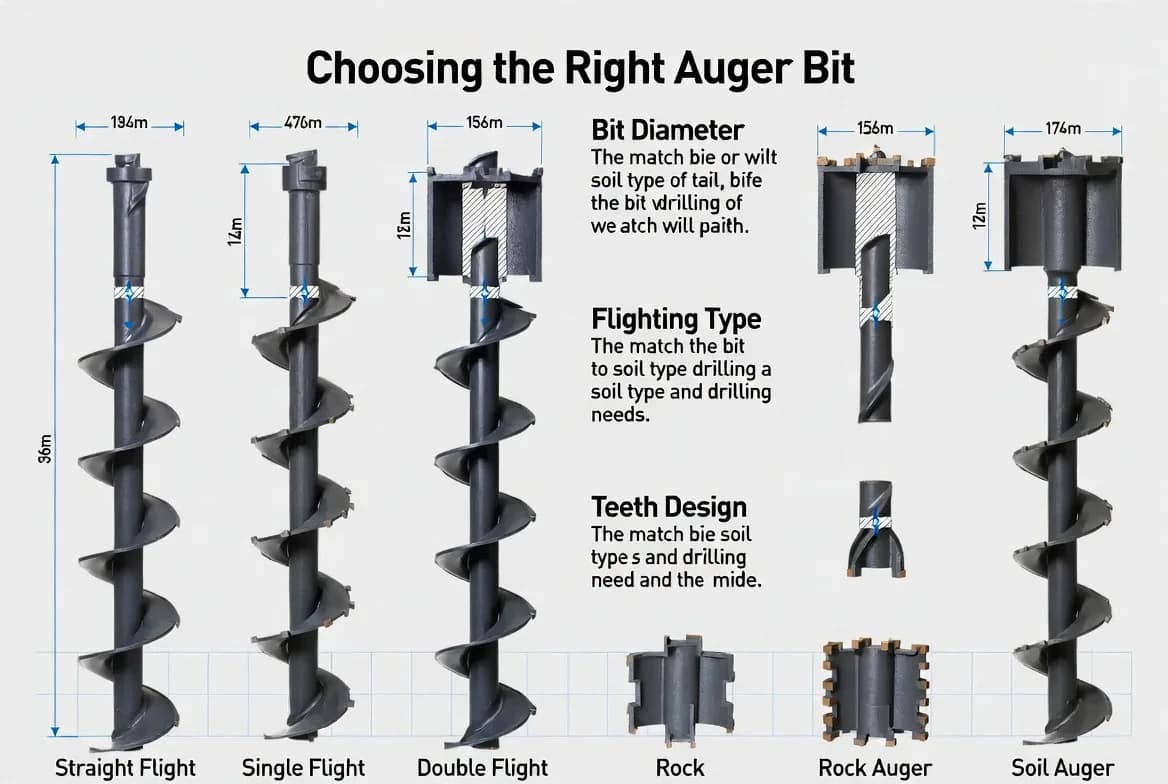
Soil augers typically use replaceable teeth and a pilot suitable for earth, clay and moderate gravel. Flighting carries cut material upward. Tooth angle and spacing should allow penetration without excessive vibration. In soft ground, aggressive teeth may cause the bit to pull in too quickly. In compacted clay, worn teeth polish the surface instead of cutting.
General-purpose bits are useful where conditions vary, but they are a compromise. Keep spare teeth and pilots available. Inspect retainers frequently. Select wear materials appropriate to abrasiveness. If large stones repeatedly stop rotation, do not force the drive at relief pressure; reassess the ground and bit.
Rock bits and specialised tools
Rock augers use stronger cutting heads, carbide or other hard inserts and geometry designed to fracture material rather than scoop soil. They require adequate torque and downforce. A rock bit is not a substitute for a dedicated drilling system in very hard or abrasive formations. Continuous operation at stall can damage the drive and carrier.
Other tools include tree bits, stump-planer heads, mixing paddles and core barrels. Each has specific speed, torque and guarding requirements. Confirm that the drive unit, shaft, coupler and carrier are approved for the tool. Specialised heads can create larger reaction forces and different debris hazards.
Flighting design and spoil removal
Flighting pitch, thickness and configuration control how spoil moves. Single flighting is common for general work. Double flighting can improve balance and spoil transport in some conditions. Heavy-duty flighting resists abrasion. The flight diameter and central shaft must remain straight. Bent flighting causes vibration and oversized or irregular holes.
Operators should withdraw periodically to clear spoil rather than filling the entire flight and overloading the system. Raise smoothly and keep people away from rotating spoil. Do not reverse or shake material toward workers. Sticky soil may require cleaning with the machine shut down and the attachment secured; never use hands or tools near a rotating auger.
Drive-unit matching
The bit must match the auger drive's output shaft, coupler and torque range. Larger diameter and harder ground require more torque, while excessive rotational speed can reduce cutting efficiency and throw material. Compare the drive's hydraulic flow and pressure requirements with the carrier. Confirm whether the machine offers a suitable bidirectional circuit and enough return capacity.
Use approved pins and retainers at the drive-to-bit connection. Check shaft size and shape. A loose or worn connection produces impact and can release the bit. The combined mass and length affect stability, especially on skid steers or mini excavators. Keep the auger low during travel and avoid side slopes.
Drilling technique and verticality
Position the carrier on firm, level ground whenever possible. Align the bit before rotation and begin at low speed. Apply only enough downforce to maintain cutting. Excessive force can bend the bit, overload bearings or cause the machine to lift. Keep the mast, boom or lift arms positioned to maintain verticality as the bit advances.
Stop rotation before repositioning. If the bit binds, relieve the load and reverse according to the approved procedure. Do not use the carrier to pry a stuck bit sideways. Monitor spoil and sound for changing ground conditions. Maintain an exclusion zone around the rotating tool and hole.
Safety around underground and overhead hazards
Drilling can contact buried electrical, gas, water, communication and drainage services. Complete required locating and verification before work. Use hand exposure or other controlled methods where rules require it. Maintain safe clearances and follow local regulations. If an unknown service is encountered, stop immediately and secure the area.
Auger assemblies can also approach overhead lines during raising or transport. Plan the movement path and maximum height. Use a spotter where visibility is limited. Open holes must be guarded, covered or otherwise controlled to prevent falls and vehicle entry.
Inspection, wear and replacement
Inspect the pilot, teeth, flighting, shaft, welds, coupler and retaining hardware before use. Replace missing or worn teeth as a set where balance requires it. Check for cracks at flighting welds and the drive connection. Remove wrapped wire, roots and debris only after isolation.
Track tooth life by ground type. Rapid uneven wear can indicate misalignment or unsuitable tooling. Store bits supported to prevent bending and protect cutting tips. After use in corrosive soil, clean and inspect. Follow approved repair procedures; poorly repaired flighting can fail at speed.
Key takeaways
Choose an auger bit from the required hole, ground conditions, drive torque, hydraulic capability, shaft connection and carrier stability. Diameter alone is not enough. Match tooth and flighting design to the material, control speed and downforce, clear spoil safely and protect against utilities and open-hole hazards. Inspect wear parts and connections before every shift. Use manufacturer limits for the drive, carrier and bit.
Torque, speed and reaction force
Large bits and hard ground require torque, while smaller bits in soft material can use more speed. Excessive speed throws spoil and increases wear; insufficient torque causes repeated stalling. Reaction torque is transferred into the carrier and can pull or rotate a small machine. Keep the carrier stable, use recommended engine and hydraulic settings and avoid sudden starts. If the machine moves instead of the bit cutting, reduce downforce, change tooling or use a more suitable carrier.
Extensions, joints and alignment
Extensions allow deeper holes but increase bending risk and make alignment more difficult. Use matched, rated extensions with correct pins and retainers. Inspect every joint for wear and straightness. Start with the shortest practical assembly and add extensions according to the approved procedure. A bent extension produces an oversized, wandering hole and severe vibration. Keep the assembly vertical and avoid using the boom to force a misaligned bit.
Water, collapsing ground and hole stability
Groundwater, loose sand and disturbed fill may cause the hole to collapse after the bit is withdrawn. This can trap the auger, reduce effective depth or create an unsafe void. The work plan may require casing, drilling fluid, a different tool or immediate placement of the post or concrete. Do not enter or reach into an unsupported hole. If water, gas, odour or unexpected material appears, stop and assess the hazard before continuing.
Production planning and spoil control
Plan where spoil will be placed and how it will be removed. Repeated piles can obstruct the carrier, hide open holes and create trip hazards. Contaminated soil may require controlled handling. Establish a drilling sequence that maintains access and prevents the machine from travelling over unsupported holes. Mark completed holes and protect them with covers or barriers. Efficient drilling includes safe spoil management, not only penetration speed.
Recovering a stuck auger
If a bit binds, stop rotation, lower engine speed and relieve the load. Use the approved reverse function while keeping the assembly aligned. Do not jerk the boom, wrap chains around the flighting or place people near the rotating tool. If the bit cannot be recovered within normal controls, isolate the machine and develop a controlled recovery plan. The plan may require excavation around the bit, different equipment or technical assistance. A rushed recovery can bend the shaft or overturn the carrier.
Quality checks after drilling
Measure hole diameter, depth, position and verticality where the installation requires it. Inspect the bottom for loose spoil and confirm that collapse has not reduced size. Record difficult ground conditions so subsequent holes can use the correct bit and method. If a hole is out of tolerance, correct it using an approved method rather than forcing the post or foundation element into place. Quality control prevents later structural and alignment problems.
Bit changes and crew coordination
Changing bits should be planned as a lifting and pinch-point task. Park the carrier securely, lower the drive, isolate hydraulics and support the bit so it cannot fall or rotate. Use the correct pin and retaining hardware and keep hands clear while holes are aligned. Where the assembly is heavy, use approved handling equipment rather than manual force. After the change, verify the connection and rotate slowly in a clear area before drilling. Clear communication between operator and ground crew is essential because an unexpected control movement can trap hands or release the bit.
Manufacturer authority: Use the current carrier and attachment manuals, approved fitment charts and service limits as the final source for ratings, settings, inspection criteria and operating procedures.
Get More Expert Guides & Updates
Subscribe for Machinery.org guide updates and product learning content.