

Chapter objective: Hydraulic-flow matching begins with three related but different ideas. Flow determines how quickly oil is delivered and therefore strongly influences attachment speed. Pressure represents the resistance the system can overcome and is closely related to available force or torque. Hydraulic power depends on both flow and pressure. An attachment that receives enough pressure but too little flow may move strongly but slowly. An attachment that receives excessive flow may overspeed, overheat or suffer seal and motor...
Understanding flow, pressure and power
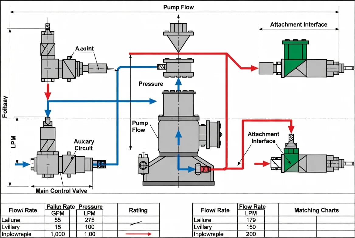
Hydraulic-flow matching begins with three related but different ideas. Flow determines how quickly oil is delivered and therefore strongly influences attachment speed. Pressure represents the resistance the system can overcome and is closely related to available force or torque. Hydraulic power depends on both flow and pressure. An attachment that receives enough pressure but too little flow may move strongly but slowly. An attachment that receives excessive flow may overspeed, overheat or suffer seal and motor damage. An attachment that requires more pressure than the machine can provide may stall or perform weakly even when the flow appears adequate.
Published values must be interpreted carefully. Carriers may list total pump flow, while only part of that flow is available at the auxiliary couplers. Attachments may list a preferred range rather than one exact number. The usable value can also change with engine speed, work mode, oil temperature and other machine functions. Matching should therefore be based on the actual auxiliary circuit, the chosen machine settings and the expected duty cycle—not on the largest number found in a brochure.
Standard flow, high flow and specialised circuits
Standard-flow circuits commonly serve general attachments such as augers, grapples, sweepers and small breakers. High-flow circuits are designed for more demanding tools such as large planers, forestry mulchers, cold planers and high-output mowers. The labels “standard” and “high” are relative; the actual litres per minute or gallons per minute vary by machine size and manufacturer. Some carriers also offer enhanced high flow at higher pressure, super-flow packages or dedicated breaker circuits.
Never connect a low-flow motor to a high-flow circuit without confirming that the machine can be limited to the attachment's range. Conversely, a high-flow attachment may physically run on a standard circuit but deliver poor production and generate heat because the operator holds the system at relief pressure. Select the correct circuit and program the machine's attachment mode where available. Record the chosen flow setting so the next operator does not unknowingly change it.
Pressure requirements and relief settings
The attachment's allowable pressure must be compatible with the carrier's auxiliary relief setting. Excessive pressure can overload cylinders, motors, seals and structural components. Insufficient pressure can reduce torque or impact performance. A machine's maximum system pressure is not necessarily the pressure present at the attachment; control valves, relief valves, hose length and operating conditions all influence the result. Pressure should be checked at the recommended test point using appropriate equipment and procedures.
Do not raise relief pressure to compensate for poor performance unless the manufacturer specifically approves the adjustment. Weak operation may result from insufficient flow, a blocked filter, worn pump, incorrect tool, excessive back pressure, internal leakage or an oversized attachment. Increasing pressure without diagnosis can hide the original problem and create a new safety risk. Record approved pressure limits and lock or protect adjustable settings where practical.
Return flow, back pressure and case drains
Many hydraulic attachments require more than a pressure supply and a normal return line. Breakers may need a low-restriction return directly to tank. High-speed motors may require a separate case-drain line to carry internal leakage back to the reservoir at very low pressure. If the case drain is blocked, connected to the wrong port or exposed to excessive pressure, motor shaft seals can fail rapidly. Some attachments require bidirectional flow, while others must rotate or cycle in one direction only.
Back pressure increases through undersized couplers, long hoses, restrictive valves, contaminated filters and small return passages. The effect becomes more severe as oil warms and flow rises. Compare the attachment's maximum permitted return pressure with the complete installed system. Use the correct flat-face or other approved couplers, keep them clean and replace damaged components. Do not substitute smaller fittings merely because they are available on site.
Hoses, couplers and pressure loss
Every component between the carrier valve and the attachment consumes part of the available hydraulic energy. Small hose diameter, excessive hose length, sharp bends, restrictive quick couplers and partially connected fittings cause pressure loss and heat. Hose selection must account for flow, working pressure, impulse loading, temperature, bend radius and abrasion. Coupler size should support the expected flow without excessive velocity.
Route hoses through the full range of lift, tilt, curl, swing and articulation before production work. Hoses should not become tight, rub on tyres or tracks, contact hot exhaust components or enter pinch points. Provide enough controlled slack for movement without allowing loops to snag. A hose that looks acceptable with the attachment on the ground may be overstretched at full height or full curl. Secure and protect the routing while preserving access for inspection.
Heat generation and cooling capacity
Hydraulic heat is a major indicator of poor matching. Energy that does not produce useful work becomes heat through relief-valve operation, internal leakage, pressure drop and inefficient operation. Continuous-duty attachments such as mulchers, trenchers and planers place much greater demand on the cooling system than intermittent cylinders. A carrier may provide the required peak flow yet still lack enough cooling for sustained production.
Monitor oil temperature according to the machine's instruments and manufacturer limits. Warning signs include repeated temperature alarms, reduced performance as the oil warms, darkened oil, seal leakage, a hot smell or hoses that are unusually difficult to touch. Clean coolers, maintain correct oil level and viscosity, and keep the work area around the cooling package free of debris. If overheating continues, reduce duty cycle, verify the hydraulic settings and investigate system restrictions rather than simply continuing at lower production.
Measuring actual performance
Published specifications are the starting point, but actual condition matters. A worn pump may not deliver rated flow. An attachment motor may have internal leakage. A relief valve may open early. A flow meter and pressure gauge can reveal whether the carrier delivers the required values under load. Testing should be completed by qualified personnel with correctly rated equipment because hydraulic injection injuries and component failure are serious hazards.
Measure at the correct oil temperature and engine speed. Record no-load and loaded readings when the procedure requires them. Compare the result with the manufacturer's test method, not an improvised benchmark. If the attachment performs correctly on one machine but not another, test both systems and compare couplers, hoses, modes and return paths. A structured measurement prevents unnecessary replacement of expensive parts.
Selecting and setting up an attachment
Start with the attachment's minimum, preferred and maximum flow and pressure. Confirm whether the duty is intermittent or continuous and whether a case drain or free-flow return is required. Identify the carrier's usable auxiliary range, programmable settings, circuit type and cooling capability. Select couplers and hoses sized for the expected flow. Program the machine at the low end of the approved range for initial testing, then increase only as needed within the limits.
Operate the attachment unloaded first. Check direction, smoothness, hose movement and leaks. Apply a light working load and listen for cavitation, relief noise, chatter or abnormal vibration. Check temperature and performance over a realistic cycle. Save the attachment preset if the carrier supports it. Label the hoses and record the settings. This setup process takes less time than repairing an overheated motor or contaminated hydraulic system.
Troubleshooting poor hydraulic performance
Slow operation may result from low flow, low engine speed, a restricted coupler, a misadjusted machine preset or internal leakage. Weak force or torque may point to low pressure, early relief, excessive leakage or an oversized tool. Rapid overheating may indicate continuous relief operation, excessive back pressure, a blocked case drain, wrong oil, dirty coolers or an attachment operating outside its range. Jerky movement can result from air, cavitation, sticky valves or unstable control signals.
Troubleshoot one variable at a time. Confirm identity and specifications, inspect connections, verify settings, check oil level and condition, examine filters and coolers, then measure flow and pressure using the approved procedure. Do not continue operating a system that produces metal debris, foaming, severe noise or repeated temperature alarms. Contamination can spread through the carrier and damage multiple components.
Key takeaways
Successful hydraulic matching requires the correct usable flow, allowable pressure, return path, case drain, hose and coupler capacity, cooling performance and machine control settings. Maximum brochure values are not enough. Begin at conservative settings, test under a controlled load and monitor temperature. Never increase pressure to mask an unidentified problem. Record the approved configuration and rely on manufacturer procedures for testing and adjustment.
Duty cycle and machine work modes
Hydraulic demand must be considered over time, not only at one instant. A grapple may use full flow for a few seconds and then rest, while a mulcher can request high power continuously. Machines often provide economy, standard, power or attachment modes that change engine speed, pump response and cooling performance. Select the mode recommended for the tool and confirm that automatic idle, regeneration or combined-function logic does not interrupt operation. For continuous duty, allow warm-up and monitor temperature throughout a representative production period. A circuit that performs well for a short demonstration may still overheat after twenty minutes. Record the tested duty cycle and any required cooling breaks so production expectations remain realistic.
Oil cleanliness and fluid compatibility
Hydraulic attachments share oil with the carrier, so contamination travels in both directions. Before connecting an unfamiliar or used attachment, inspect the oil condition and clean the couplers. Where contamination is suspected, sample or flush the attachment according to an approved procedure. Confirm that seals and motors are compatible with the carrier's fluid type and temperature range. Mixing incompatible oils can affect viscosity, additives and seal life. After a motor or pump failure, do not simply install a replacement and reconnect; debris may remain in hoses, manifolds and the case-drain circuit. Cleanliness targets, filter ratings and flushing requirements should come from the manufacturer or a qualified hydraulic specialist.
Manufacturer authority: Use the current carrier and attachment manuals, approved fitment charts and service limits as the final source for ratings, settings, inspection criteria and operating procedures.
Get More Expert Guides & Updates
Subscribe for Machinery.org guide updates and product learning content.