
Mini excavators are best known for digging, but they are also used every day to lift trench boxes, pipes, landscape materials, concrete pieces, attachments, and other jobsite loads. That versatility is valuable only when the operator understands the machine’s limits. A mini excavator does not have one fixed lifting capacity. Its ability changes with boom position, arm reach, lift height, load radius, attachment weight, undercarriage position, and ground conditions. A load that feels stable close to the blade may become unsafe when the same load is extended farther away or swung over the side.
This guide explains how to think about lifting capacity in practical terms. It is not a substitute for the manufacturer’s lift chart or operator manual. Those documents remain the final authority for the exact model, boom, arm, counterweight, blade position, and attachment configuration. The purpose here is to help buyers and operators understand why the numbers change, how to read a load chart more intelligently, and how to prepare a safer lifting setup before the hook or sling ever takes weight.
The most important mindset is simple: lifting with an excavator is a stability problem as much as a hydraulic-power problem. A machine may have enough hydraulic force to raise a load but still lack the stability to control it. Safe lifting therefore requires both sufficient hydraulic capacity and a stable working geometry.

Figure 21.1. Machinery.org lifting-capacity overview showing how reach, boom position, load radius, and ground conditions affect safe lifting.
What lifting capacity really means
Lifting capacity is the maximum load the machine can safely raise at a defined working radius and height under specified conditions. The value normally includes important assumptions, such as the blade position, whether the lift occurs over the front or over the side, the installed bucket or coupler, and the type of lifting point used. Some charts show hydraulically limited values, while others are limited by tipping stability. The lower limit is the one that governs.
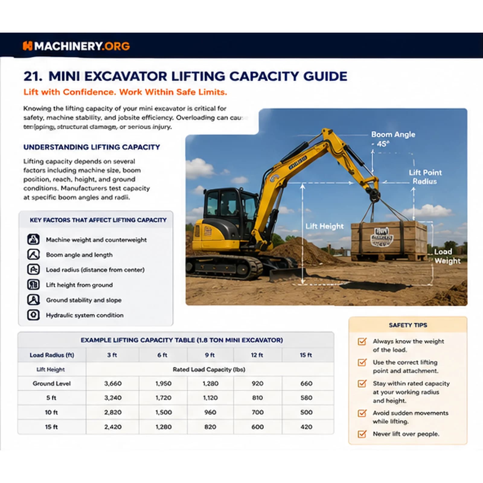
Working radius is measured from the machine’s swing center to the lifting point or load line. As radius increases, leverage against the machine increases and rated capacity usually decreases. This is why a load that is manageable at three feet from the machine may be unsafe at ten or twelve feet. Lift height also changes the geometry. High lifts, low lifts below ground level, and side lifts each create different load paths through the boom, arm, cylinders, house, and undercarriage.
The main factors that change capacity
Machine weight and counterweight
Heavier machines and machines equipped with appropriate counterweights generally have greater stability, but weight alone does not guarantee safe lifting. The undercarriage width, tail configuration, boom length, and center of gravity also matter. Adding an attachment or coupler can change the center of gravity and subtract from the net load that can be safely handled.
Boom, arm, and load radius
Longer arms increase reach but normally reduce lifting capacity at the same machine size because the load acts farther from the swing center. The boom angle and arm position also influence leverage. Keeping the load close to the machine and avoiding unnecessary extension is one of the most effective ways to improve stability.
Undercarriage and blade position
For many mini excavators, lifting over the blade with the blade lowered can improve stability. Lifting over the side is usually more restrictive because the track width provides a smaller stability base in that direction. Expandable undercarriages should be fully extended when the manufacturer recommends it. The machine should sit level, with both tracks supported on firm ground.
Attachment, coupler, and rigging weight
The rated load must account for everything hanging from the boom: bucket, quick coupler, lifting eye, hook, sling, chain, spreader, and the load itself. A heavy hydraulic coupler and bucket can consume a meaningful portion of available capacity. Operators should calculate the net load instead of comparing only the object weight with the chart value.
How to use a lift chart
Confirm the exact machine model, arm length, counterweight, blade configuration, and attachment setup.
Identify the planned lift direction: over the front, over the blade, or over the side.
Measure or estimate the working radius from the swing center to the load line.
Determine the expected lift height and whether the load begins below grade, at ground level, or above ground.
Find the chart cell that matches radius, height, and direction, then apply the lowest applicable limit.
Subtract bucket, coupler, lifting device, and rigging weight to calculate the net object weight that can be handled.
Never average between optimistic values or assume that a nearby chart cell is close enough. If the planned lift sits between chart positions, use the more conservative value. Unknown load weight is another major risk. When possible, use shipping documents, scale information, engineering data, or supplier specifications rather than visual estimates.
Safe lifting setup
Inspect the lifting eye, hook, coupler, pins, boom, arm, cylinders, and hydraulic hoses before the lift.
Use rated slings, chains, shackles, and hooks with readable identification and adequate working-load limits.
Keep the travel path clear and establish a controlled work zone around the machine and load.
Use a trained signal person when the operator cannot see the load or landing area clearly.
Lift slowly, avoid shock loading, and keep the load as low and close to the machine as practical.
Do not travel with a suspended load unless the manufacturer allows it and the procedure is properly planned.
Never lift people with an excavator unless the machine and approved platform are specifically designed and authorized for that use.
Common mistakes
Common errors include lifting with the undercarriage partially retracted, using an unrated bucket tooth as a lifting point, ignoring the weight of the quick coupler, swinging a heavy load rapidly, lifting on a slope, and relying on hydraulic strength as proof of stability. Another frequent mistake is beginning a lift with the load hidden in a trench. If the object is stuck in soil or connected to unseen material, breakout resistance can create forces far higher than the object’s listed weight.
Planning the lift before work begins
A good lift plan does not need to be complicated for a routine task, but it should answer basic questions: What does the load weigh? Where is the center of gravity? What is the farthest radius? Where will the machine sit? Is the ground firm? Which lifting point and rigging will be used? Who will signal? Where will the load be landed? If any answer is uncertain, pause and resolve it before applying load.
For repeated work, such as pipe placement or landscape-block installation, operators should standardize the safest setup. Mark preferred machine positions, establish maximum practical reach, use consistent rigging, and train the crew to recognize when changing ground conditions or load sizes require a new assessment.
Buying considerations for lifting work
Buyers who expect frequent lifting should compare more than engine power and digging depth. Review published lift charts, undercarriage width, blade geometry, counterweight options, hydraulic smoothness, visibility, certified lifting points, and available warning devices. A machine that is slightly heavier but more stable may be a better business choice than a lighter machine with attractive transport weight but limited lifting confidence.
The best lifting machine is not necessarily the machine with the largest headline number. It is the machine that provides usable capacity at the radius, height, and direction your work actually requires.

Figure 21.2. Machinery.org safe-lifting guide with load examples, decision factors, and operating reminders.
Frequently Asked Questions
Can a mini excavator lift more with the blade down?
Often yes, especially when lifting over the blade, but the exact benefit depends on the model and load chart. Always follow the manufacturer’s specified setup.
Does removing the bucket increase lifting capacity?
Removing a heavy bucket can increase net available capacity, but the approved lifting point, coupler weight, and chart configuration still control the lift.
Why is side lifting usually more limited?
The machine has a narrower stability base over the side than over the length of the tracks, so tipping resistance is lower.
Key Takeaway
Safe lifting depends on geometry, stability, and correct load information. Keep the load close, use the exact lift chart, include all attachment and rigging weight, and never treat hydraulic power as proof that the lift is safe.
Get More Expert Guides & Updates
Subscribe for Machinery.org guide updates and product learning content.