
Chapter objective: The mounting system is the physical connection that transfers attachment weight, payload, digging forces, impact and vibration into the carrier. It must locate the attachment accurately, resist movement in every working direction and remain locked throughout the operating cycle. A connection that appears close enough can still be unsafe if the pin centres, ear width, hook profile or latch depth differ by only a small amount. Under load, that difference can produce movement, concentrated stress or incomplete...
Why the mounting interface matters
The mounting system is the physical connection that transfers attachment weight, payload, digging forces, impact and vibration into the carrier. It must locate the attachment accurately, resist movement in every working direction and remain locked throughout the operating cycle. A connection that appears close enough can still be unsafe if the pin centres, ear width, hook profile or latch depth differ by only a small amount. Under load, that difference can produce movement, concentrated stress or incomplete engagement.
Mounting compatibility should therefore be treated as a dimensional and functional verification. The exact machine model, coupler model, attachment interface and any adapter must be identified. The system should be checked against manufacturer drawings or fitment charts and inspected for wear or modification. The purpose is not merely to make the attachment connect; it is to ensure that the load path and locking mechanism operate exactly as intended.
Pin-on excavator attachments
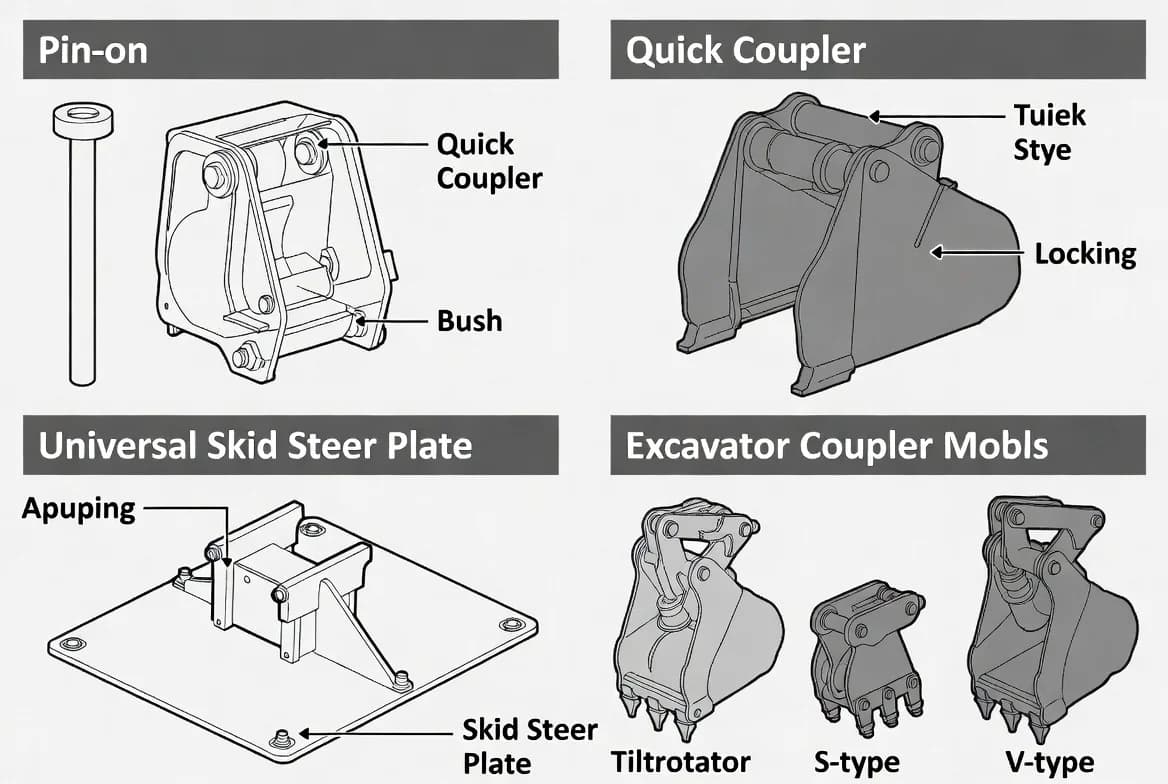
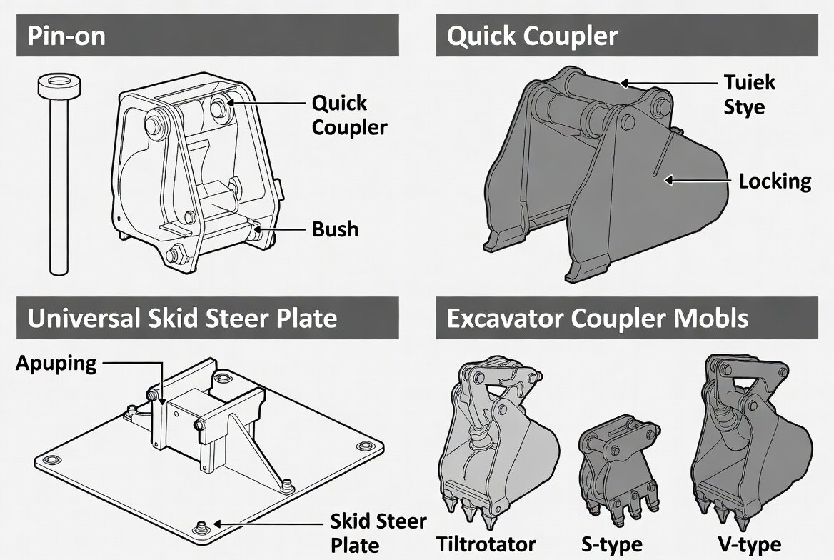
Traditional pin-on excavator attachments connect directly to the arm and linkage with pins. Important dimensions include pin diameter, distance between pin centres, width between the attachment ears and the geometry of the linkage connection. Two attachments may share a pin diameter yet differ in centre distance or ear spacing. Even when pins can be inserted, incorrect geometry can reduce curl range, cause interference, alter breakout performance or overload the linkage.
Pins and bores must be in serviceable condition. Worn bores create impact loading and poor control. Incorrect pin material or retention can allow movement and eventual loss. Use the specified pins, bushes, retainers and lubrication. Never use undersized pins, loose bolts or temporary bars as operating substitutes. After installation, move slowly through the full range and confirm that the attachment, linkage, hoses and quick-coupler components do not collide.
Excavator quick couplers
Quick couplers reduce changeover time but introduce additional geometry and locking components. Coupler families may be dedicated, pin-grabber, wedge, S-type, V-type or manufacturer-specific. A coupler may accept several pin spacings but still have limits for pin diameter, ear width and attachment shape. Some systems require specially prepared attachment brackets. Others can pick up conventional pin-on tools within a defined range.
Identify the coupler model and serial number, not only the machine. Confirm approved attachment dimensions and the correct operating procedure. Primary and secondary locks must engage as designed. The operator should be able to see or otherwise verify the lock indicator. If the coupler relies on hydraulic pressure, it must still include the required mechanical retention or safety device. Wear at hooks, wedges and pins can reduce engagement; measure against service limits rather than relying on appearance alone.
Skid-steer and compact-loader plates
Many skid steers and compact track loaders use a common quick-attach plate, but actual fit can still be affected by damaged latch pockets, bent plates, thick paint, debris or poor manufacturing tolerances. The attachment should seat fully against the carrier plate, and both locking pins should extend through the lower pockets. Partial pin engagement is not acceptable.
Inspect the top lip, lower pockets, locking pins, springs, handles and surrounding welds. A bent attachment plate can place the load on one side and cause cracking. Verify that hydraulic hoses do not prevent the plate from seating. After connection, tilt the attachment forward close to the ground and apply gentle pressure to confirm retention, following the machine manufacturer procedure. Do not travel or lift until both pins are visually confirmed.
Loader, telehandler and forklift interfaces
Wheel loaders, telehandlers and forklifts use a variety of carriages, hooks, pins and quick-hitch systems. A tool may fit the width of a carriage but have the wrong hook profile or locking-pin position. Telehandler attachments can change the rated capacity and require a dedicated load chart. Forklift attachments may change the load centre and residual capacity. Loader quick couplers may be manufacturer-specific even when the machines are similar in size.
Confirm the exact interface standard and the attachment's approved carrier list. Check automatic locking indicators and manual retaining pins. Where hydraulic locking is used, inspect cylinders, hoses and check valves. Never assume that an attachment borrowed from another fleet machine is acceptable. The load chart, attachment plate and operating manual should identify the approved combination.
Adapters: benefits and consequences
Adapters can connect different mounting families, but they add weight, length, joints and potential movement. The increased distance from the carrier changes leverage and may reduce lifting capacity, breakout force and stability. An adapter also adds another set of locks that must be inspected. The combined geometry may create interference or reduce attachment range.
Use only engineered, rated adapters approved for the intended machines and attachments. Include the adapter mass in all capacity calculations. Inspect welds, pins, hooks and locking mechanisms before use. Do not stack multiple adapters unless explicitly approved. Avoid site-fabricated adapters without engineering documentation. A convenient connection is not automatically a safe load path.
Inspection and wear limits
Daily inspection should cover cracks, deformation, missing retainers, worn pins, elongated bores, damaged hooks, loose fasteners, leakage and contamination around locking surfaces. Clean the interface before connection. Dirt, ice, compacted material and hardened grease can prevent full engagement. Lubricate points according to the specified schedule, but do not allow grease to hide cracks or block indicators.
Periodic inspection should include measurement. Pins, bushes, wedges and hooks have service limits. Excessive clearance produces shock loading and can allow a lock to disengage. Keep records of measured wear so replacement can be planned. If a mounting component has been welded or modified, verify that the repair follows an approved procedure and that heat has not damaged critical material properties.
Connection and functional-check procedure
Park on firm, level ground and keep people clear. Inspect both interfaces. Align the carrier squarely, connect according to the approved sequence and activate the lock. Verify the primary and secondary retention visually or by the designated indicator. Route hoses and cables. Then conduct a controlled functional test with the attachment close to the ground. Curl, tilt or crowd the attachment gently to confirm secure engagement.
Move through the operating range at low speed and check for interference. Stop if the attachment shifts, the lock indicator changes, the pins do not seat fully or unusual noise occurs. Recheck after the first short work period because debris may settle and new movement may become visible. A consistent procedure reduces dependence on memory and prevents rushed changeovers.
Common mistakes
Frequent errors include matching only by carrier weight, using pins that happen to fit, failing to account for an adapter, operating with one skid-steer latch pin engaged, relying on hydraulic pressure as the only retention, ignoring worn hooks, modifying brackets without approval and failing to test the connection. Another common mistake is assuming that a coupler fitted to the machine at delivery has never been replaced. Always identify the installed component.
If dimensions or approval information cannot be confirmed, do not improvise. Mark the combination as not verified and obtain the correct drawing or fitment statement. The cost of delay is small compared with a dropped attachment or damaged boom.
Key takeaways
Mounting compatibility depends on exact geometry, correct locking and acceptable condition. Pin-on tools, excavator couplers, loader plates and telehandler carriages are not interchangeable merely because they appear similar. Adapters require their own rating and reduce capacity through added weight and leverage. Clean, inspect, connect, verify and function-test every change. Manufacturer drawings and approved fitment information remain the authority.
Identification and configuration control
Fleet records should identify the mounting system as carefully as the carrier itself. Record coupler manufacturer, model, serial number, pin range, locking type and any software or hydraulic kit. Attachments should have readable plates or tags showing bracket family and weight. When a coupler is replaced, update every related compatibility record. This matters in fleets where identical carriers have different couplers or where hired equipment arrives with an unfamiliar interface. A simple photograph of the coupler and attachment bracket can prevent selection errors, but photographs should support—not replace—dimensioned documentation.
Transport, storage and handling of unattached tools
Mounting surfaces are easily damaged when attachments are dragged, dropped or stored directly on uneven ground. Provide stable stands that keep pins, hooks, plates and hoses clear of dirt and impact. Secure tools during transport so they cannot move and deform the interface. Cap hydraulic connections and protect electrical plugs. When lifting an unattached tool, use designated lifting points rather than coupler pockets unless those pockets are specifically rated. Inspect the interface again after transport because a small bend or damaged latch pocket can prevent full engagement.
Procurement and fleet standardisation
A fleet can reduce risk and downtime by standardising coupler families where practical. Before buying an attachment, verify the exact interface and future carrier plan rather than ordering a generic bracket. Include required adapters, hose kits, pins, control kits and documentation in the purchase specification. Standardisation should not encourage forced interchangeability; it should make approved combinations easier to identify. Maintain a controlled list of compatible carrier-attachment pairs and remove obsolete combinations when machines or couplers are sold or modified.
Field acceptance after a mounting change
Whenever a new coupler, adapter or attachment bracket is installed, complete a formal acceptance check before production. Confirm dimensions, lock operation, range of motion, hose clearance and the effect on lifting geometry. Test with the attachment close to the ground and inspect again after the first working period. Record the accepted configuration and place any limitations where operators can find them. A mounting change should never enter normal service only because the parts assembled successfully in the workshop.
Manufacturer authority: Use the current carrier and attachment manuals, approved fitment charts and service limits as the final source for ratings, settings, inspection criteria and operating procedures.
Get More Expert Guides & Updates
Subscribe for Machinery.org guide updates and product learning content.