

Chapter objective: Quick couplers improve productivity by allowing attachments to be changed without manually removing pins, but the convenience can create a false sense of security. A coupler that appears connected may not be fully engaged. The attachment can remain in place during light movement and then separate when curled, lifted or shaken. Dropped attachments can crush workers, strike vehicles, damage utilities and destabilise the...
The risk behind faster attachment changes
Quick couplers improve productivity by allowing attachments to be changed without manually removing pins, but the convenience can create a false sense of security. A coupler that appears connected may not be fully engaged. The attachment can remain in place during light movement and then separate when curled, lifted or shaken. Dropped attachments can crush workers, strike vehicles, damage utilities and destabilise the carrier.
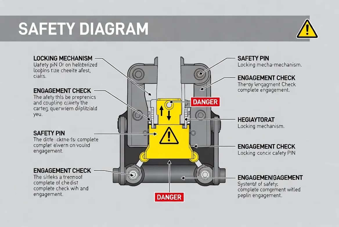
The core safety principle is that connection is not complete until both the primary locking mechanism and the required secondary retention are confirmed. The verification must be physical or through a reliable indicator defined by the manufacturer. Hydraulic pressure alone is not a substitute for mechanical retention. Every operator should use the same documented connection and test sequence, regardless of experience or production pressure.
Know the coupler type and controls
Couplers differ in design. Some are dedicated to one attachment bracket; others grip existing pins. Some use a hydraulic wedge, hook or latch. Some include a manual safety pin, an automatic secondary lock or a visual indicator. The cab control may require a specific sequence, safety switch or confirmation. An operator trained on one design should not assume another operates the same way.
Identify the coupler make, model and operating instructions. Confirm the meaning of lights, alarms and indicators. Understand what happens if hydraulic pressure is lost. Know whether the attachment can be released only in a particular position. Keep the instructions in the machine and include the coupler in familiarisation training for every operator.
Pre-connection inspection
Before approaching an attachment, inspect the coupler and attachment pins or brackets. Remove mud, stone, ice and compacted debris from hooks, wedges and locking areas. Check for cracks, bent parts, missing retainers, damaged hoses, leakage, worn pins, worn hooks and an unreadable indicator. Confirm that the attachment dimensions are within the coupler's approved range.
The attachment should be positioned on firm ground where it cannot roll or tip. Keep people out of the change area. If a safety pin or manual device is required, make sure it is available and in serviceable condition. Do not begin a change when visibility is poor or the work area is unstable. A clean, controlled setup is the first defence against incomplete engagement.
The align-engage-verify-test sequence
Use a four-stage procedure. Align the coupler squarely with the attachment. Engage the front hook, pin or bracket fully. Activate the lock according to the approved control sequence. Verify the primary and secondary locking devices. Then perform the specified test close to the ground.
Verification should include the visual indicator, mechanical safety device and the relationship of the coupler to both attachment pins or brackets. The functional test may involve curling or crowding the attachment against the ground with controlled force. The purpose is to prove that the attachment cannot separate, not to shock-load the system. If visibility from the cab is limited, position the machine safely and obtain an external check according to site procedure, with the attachment lowered and the machine secured.
Secondary retention and independent safety
A secondary lock is intended to retain the attachment if the primary mechanism is incomplete or fails. Its design and operation vary. It may be an automatic mechanical latch, a safety pin, a separate wedge or another independent feature. The operator must know how to confirm its engagement. A device that is present but not checked provides little protection.
Never wire, block or bypass a secondary mechanism. Do not operate with a missing safety pin because the attachment “has never fallen off before.” If the secondary lock is difficult to install, identify the cause—misalignment, wear, debris or the wrong attachment. Correct the fault rather than normalising an unsafe condition.
Working practices after connection
Keep the attachment low during initial movement and recheck the lock after the first operating cycles. Avoid carrying workers or allowing people beneath a raised attachment. Establish an exclusion zone during changeover and testing. When practical, position the machine so a possible release would fall away from people, structures and live services.
Operate smoothly. Excessive shaking, side loading and impact accelerate wear at the coupler and pins. If the attachment develops unexpected movement, noise or a changed indicator, lower it immediately and stop. Never attempt to repair or inspect a raised attachment without approved support and isolation.
Inspection, maintenance and wear
Clean and inspect the coupler daily. Lubricate pins, wedges and pivots at the specified interval. Check hydraulic cylinders, hoses, valves and electrical indicators. Measure wear at hooks, pins and locking surfaces according to the service manual. Replace components before clearance reaches the rejection limit.
Repairs to load-bearing coupler components require approved parts and procedures. Unauthorised welding or grinding can alter geometry and material strength. After maintenance, complete a full function and retention test before returning the machine to service. Record repairs and inspections, especially where the coupler is used by multiple operators or on rented equipment.
Human factors and supervision
Many coupler incidents involve interruption, hurry, poor visibility or an operator assuming the lock has engaged. Design the procedure to resist these human errors. Use a simple checklist, clear indicators and a standard test every time. Avoid phone or radio interruptions during the final connection steps. Supervisors should observe changeovers periodically and correct drift from the procedure.
Training should include practical demonstrations of incomplete engagement, indicator meanings and the correct response to alarms. Operators should be encouraged to stop without penalty when a connection cannot be confirmed. Production targets must never override the lock check.
Emergency and incident response
If an attachment separates or the lock is suspected to have failed, stop the machine, lower all equipment, isolate the area and report the event. Do not reconnect and continue without determining the cause. Inspect the coupler, attachment, pins, hydraulic system and surrounding structure. Preserve relevant information such as photos, machine settings and witness reports.
A near miss should be investigated as seriously as a drop. It may reveal wear, training gaps, unclear indicators or an incompatible attachment. Corrective action can include component replacement, updated procedures, operator retraining and fleet-wide inspection of similar couplers.
Key takeaways
Quick-coupler safety depends on a consistent align, engage, verify and test sequence. Both primary and secondary retention must be confirmed. Cleanliness, correct geometry, inspection and wear measurement are essential. No person should enter the danger area or stand under an attachment. If the lock cannot be positively verified, the machine must not work. Follow the coupler and carrier manufacturer instructions for the exact installed system.
Changeover risk assessment
The location and timing of a changeover affect risk. Choose firm, level ground with enough room to align squarely and test the attachment. Keep pedestrians and other machines outside a defined exclusion zone. Avoid changing on traffic routes, steep slopes, trench edges or beneath overhead work. If the attachment is unstable, place it on suitable supports before release. The operator should pause other tasks and complete the lock sequence without interruption. A short pre-change assessment is especially important when attachments are muddy, unusually heavy or connected for the first time.
Poor visibility, darkness and weather
Rain, snow, dust, glare and darkness can hide pins and indicators. Provide clean lighting and mirrors or cameras where approved. Remove ice and compacted material from locking surfaces; never use the coupler to crush ice into place. If the engagement point cannot be clearly seen, lower the attachment, secure the machine and obtain a safe external inspection. The checker must remain outside the crush zone and communicate through an agreed signal or radio method. Work should stop when conditions prevent positive verification.
Alarms, indicators and interlocks
Visual and audible indicators are aids, not substitutes for understanding the mechanism. Operators must know what each light or alarm means during locking, unlocking and fault conditions. Test indicators during scheduled maintenance and investigate intermittent signals. Never silence an alarm permanently or bridge an interlock to maintain production. If a control system reports a lock fault, lower the attachment and follow the diagnostic procedure. A failed sensor can be dangerous because it may provide false reassurance or prevent the system from completing its safe sequence.
Supervision and periodic auditing
Supervisors should periodically observe attachment changes and compare practice with the written procedure. Look for skipped visual checks, people entering the danger area, hurried testing or reliance on one indicator. Review near misses and unusual wear for signs of incomplete engagement. Refresher training is valuable after a new coupler is introduced, an incident occurs or seasonal workers return. Audits should focus on learning and correction, not only discipline, so operators report difficult locks and unclear instructions before a drop occurs.
Procurement and retrofit considerations
When selecting or retrofitting a quick coupler, consider independent retention, visibility of lock status, compatibility range, maintenance access and the consequences of hydraulic or electrical failure. Obtain approved installation instructions and confirm that the carrier's hydraulic and control system is suitable. After installation, verify geometry, pressure settings, warning devices and attachment range. Update load or lifting information for the added coupler weight and geometry. A coupler should not be accepted solely because it speeds changeovers; its safety features must be practical for operators to verify every time.
End-of-shift control
At the end of work, lower the attachment onto stable ground, release stored energy and leave the coupler in the condition specified by the manufacturer. Report any difficult engagement, indicator fault or unusual movement before another operator uses the machine. A short handover note can prevent the next shift from treating an unresolved lock problem as normal behaviour.
Manufacturer authority: Use the current carrier and attachment manuals, approved fitment charts and service limits as the final source for ratings, settings, inspection criteria and operating procedures.
Get More Expert Guides & Updates
Subscribe for Machinery.org guide updates and product learning content.