
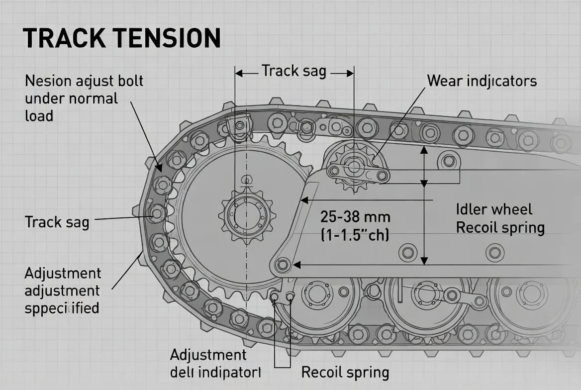
Track tension controls undercarriage loading, derailment risk, traction, and wear; both excessive tightness and excessive looseness shorten component life.
CHAPTER FOCUS
track chain, pins and bushings, sprocket, front idler, carrier rollers, bottom rollers, and track adjuster
Why This Topic Matters
Track-Tension Inspection is a core part of reliable heavy-equipment ownership because small changes in condition can develop into safety incidents, component damage, lost production, or expensive secondary failures. Track tension controls undercarriage loading, derailment risk, traction, and wear; both excessive tightness and excessive looseness shorten component life. A disciplined program does more than satisfy a service schedule: it creates evidence about how the machine is aging and gives operators and technicians time to intervene before a defect becomes urgent.
The goal is to measure track sag in the manufacturer-specified posture, account for packed material and operating conditions, adjust safely, and use wear patterns to identify underlying problems. The strongest maintenance programs connect the operator's daily observations with technician measurements, service history, parts usage, and manufacturer guidance. Decisions should be based on the exact model, serial range, configuration, environment, and duty cycle. Generic intervals and values are useful only as orientation; the operator's manual and service information remain the controlling references for capacities, limits, approved materials, and safety procedures.
System Fundamentals
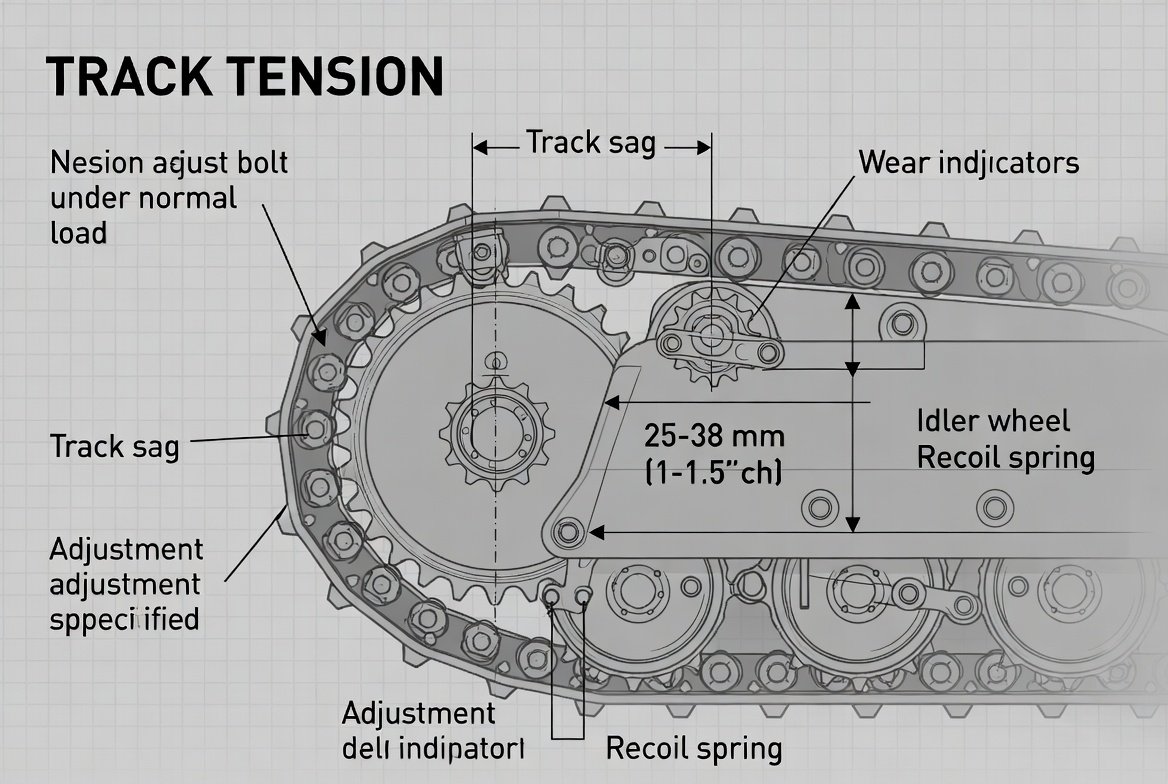
The relevant system includes track chain, pins and bushings, sprocket, front idler, carrier rollers, bottom rollers, track adjuster, recoil spring, track shoes, and final drive. These parts should not be considered independently. A restriction, leak, incorrect adjustment, electrical command, contaminated fluid, or damaged mechanical interface in one area can create symptoms elsewhere. Understanding the flow of energy and material through the system helps prevent the common mistake of replacing the most visible component rather than finding the originating cause.
Build a simple mental model before performing work. Identify what enters the system, what controls it, what work it performs, how heat and contamination leave, and which measurements prove correct operation. For track-tension inspection, the technician should know the normal operating state, the expected sequence of events, and the safeguards that prevent uncontrolled movement, pressure release, fire, chemical exposure, or mechanical injury.
Safety and Preparation
Prepare the machine on firm, stable ground and follow site isolation rules. Lower implements, neutralize stored energy, apply the parking brake, stop the engine, remove the key, and use lockout or tagout where the task requires it. Chock, block, or support components only with devices rated for the load. Never work beneath an unsupported attachment or rely on hydraulic pressure to hold a raised structure.
Use the personal protective equipment specified for the task and chemical. Typical preparation may include gloves, eye or face protection, protective footwear, suitable clothing, spill-control materials, and adequate ventilation. High-pressure hydraulic fluid, hot coolant, batteries, rotating fans, pressurized grease adjusters, fuel systems, and exhaust aftertreatment can cause severe injury. If the procedure requires specialized testing or exposure to stored pressure, stop and use qualified personnel.
Tools, Materials, and Technical References
Prepare the required information and equipment before opening the machine. Useful items include manufacturer measurement method, straightedge or string line, rule or tape, cleaning tools, grease gun with correct grease, approved pressure-release tools, blocking and lifting equipment where specified, and eye and hand protection. Tools must be clean, correctly rated, calibrated where measurement accuracy matters, and suitable for the machine's pressure, voltage, temperature, or load. Improvised adapters and unverified instruments can create both bad data and unsafe conditions.
Confirm the exact model and serial number, then obtain the current operator's manual, maintenance chart, service procedure, fluid or lubricant specification, torque information, and safety bulletins that apply. Record model-specific values on the work order instead of relying on memory. If a document conflicts with a decal or later manufacturer instruction, resolve the difference before continuing.
Step-by-Step Professional Procedure
Use a fixed sequence so that each step creates information for the next. The first half of the process is: 1) Park on firm level ground, clean packed material, position the machine exactly as stated in the manual, and isolate it safely. 2) Inspect shoes, bolts, chain links, bushings, rollers, idler, sprocket teeth, guards, final-drive area, and adjuster for wear, cracks, leaks, or heat. 3) Move the machine as specified to remove slack from the correct side, then measure sag at the defined point without guessing. 4) Compare the result with the model-specific range, considering whether the manual provides a special setting for mud, snow, or other conditions.
Continue with the remaining process: 5) Add grease slowly through the adjuster fitting to tighten, watching movement and never exceeding the required sag. 6) To loosen, follow the exact pressure-release procedure and keep the body away from the fitting because grease can be stored at dangerous pressure. 7) Recheck both tracks, travel slowly, listen for binding or slap, and inspect again after operating in the actual material. 8) Record measurements, adjustments, undercarriage wear, and recurring differences between sides. Complete the work with a final visual inspection, removal of tools and rags, restoration of guards, and a controlled functional test. Any step that cannot be verified should be marked incomplete rather than assumed satisfactory.
What Normal Condition Looks Like
Normal condition is established through repeatable observation rather than a single impression. Expected indicators include sag within the specified range, smooth rotation, even wear, no abnormal heat, no missing shoe bolts, adjuster holds position, sprocket and bushings wear consistently, and no derailment marks. A normal result should agree with the machine's history and operating environment. For example, an acceptable temperature or pressure at idle may not prove that the machine can control heat or deliver performance under rated load.
Create a baseline after purchase, major repair, or recommissioning. Record measurements, photographs, fluid condition, component clearances, cycle times, voltage, pressure, temperature, or other relevant values while the machine is known to be healthy. Future checks then compare against both manufacturer limits and the machine's own trend. A change within the published limit can still deserve attention when it is rapid or unexplained.
Warning Signs and Failure Clues
Conditions that require investigation include track repeatedly loosens, grease leakage at adjuster, sharp or hooked sprocket teeth, seized roller, uneven side wear, tight spots, cracked shoes, loose bolts, track riding on flanges, and final-drive leak. Observe when the symptom occurs and what changes it. Note whether it appears only when cold, hot, loaded, traveling, turning, using a particular attachment, operating on a slope, or after a service action. Timing and operating context often separate several possible causes that otherwise look similar.
Do not erase evidence before documenting it. Photograph leaks, residue, damaged parts, warning displays, smoke, wear patterns, or contaminated filters before cleaning. Record odors, sounds, vibration, temperature, and operator comments using precise language. 'Weak,' 'hot,' or 'noisy' is less useful than a description of which function changed, by how much, and under what conditions.
Common Maintenance and Diagnostic Mistakes
Frequent errors include measuring with mud packed in the frame, using a generic sag value, adjusting on a slope, standing in line with the grease fitting, making the track tight to prevent derailment, ignoring different left-right wear, and operating with seized rollers. These mistakes usually occur because the task appears routine or production pressure encourages shortcuts. A checklist is valuable precisely because experienced people can overlook familiar details, especially when working at night, in bad weather, or after an interruption.
Avoid changing several variables at once during diagnosis. Replacing filters, adjusting valves, adding fluid, clearing codes, and changing operating settings simultaneously can hide the real cause. Make one controlled change, record it, and repeat the test. Parts should be replaced because evidence identifies them as failed or because an approved preventive interval requires replacement, not because they are convenient suspects.
Severe-Duty and Environmental Adjustments
Maintenance frequency and acceptance criteria may need adjustment for mud, sand, rock, snow, demolition debris, side-slope work, long travel, and high-impact turning. Severe duty can increase contamination, heat, condensation, corrosion, vibration, impact loading, and service consumption. Short calendar intervals may be necessary even when hour accumulation is low, while continuous high-load operation may justify closer temperature and fluid monitoring.
Environmental controls are part of maintenance. Clean fueling and lubrication equipment, protected storage, suitable covers, drainage, dust control, wash procedures, and correct warm-up or cool-down practices reduce the contaminant load entering the machine. Record the actual environment so interval changes are supported by evidence rather than habit.
Measurement, Testing, and Interpretation
Use measurements to confirm observations. Select the test condition specified by the manufacturer, including fluid temperature, engine speed, machine posture, attachment, load, and control mode. Compare results with the correct units and configuration. A value taken under the wrong condition can appear precise while being technically meaningless.
Interpret trends and relationships, not only pass-or-fail limits. Rising temperature with stable load, increasing filter restriction, changing fluid-consumption rate, greater voltage drop, longer cycle time, or repeated need for adjustment may signal deterioration before a hard limit is exceeded. When results are ambiguous, repeat the test with verified equipment or involve a technician familiar with the system.
Record-Keeping and Trend Analysis
A useful maintenance record includes left and right sag, measurement posture, hours, operating material, grease added or released, roller and sprocket condition, shoe-bolt checks, wear measurement, and repair recommendation. Records should identify who performed the work, the machine hours, the exact products and parts used, measurements before and after service, and any remaining condition. Attach photographs, laboratory reports, fault-code printouts, invoices, and calibration information where relevant.
Good records support warranty claims, planned downtime, parts forecasting, resale value, and root-cause analysis. They also reveal repeat failures that individual work orders hide. Review recurring leaks, filter changes, battery replacements, overheating events, adjustments, and fluid additions by machine and by site. Repetition usually indicates an unresolved cause, unsuitable operating practice, or a maintenance-process weakness.
When to Stop and Escalate
Stop work and escalate when there is evidence of failed adjuster, recoil spring damage, cracked chain link, seized roller, repeated derailment, final-drive leak, unsafe grease pressure release, and structural undercarriage damage. The machine should remain out of service when a defect affects steering, braking, load holding, structural integrity, fire protection, operator protection, uncontrolled movement, or a manufacturer prohibition. Production urgency does not change the energy stored in the machine or the consequence of failure.
Escalation should be specific. State the symptom, measurements, operating condition, actions already taken, and the reason the machine is unsafe or requires specialist testing. Protect the evidence, isolate the machine, and identify the person authorized to approve return to service. A clear handover prevents the next person from unknowingly restarting an incomplete diagnosis.
Practical Field Example
An excavator working in sticky clay begins to travel heavily. The tracks appear tight, but cleaning reveals packed clay forcing the chain outward. After cleaning, measured sag is actually below the minimum. Correct adjustment reduces load on the final drives and prevents accelerated pin and bushing wear.
The important lesson is the method rather than the specific component. The operator recognized a change, preserved evidence, avoided an unsafe shortcut, and connected the symptom to the wider system. The maintenance response confirmed the cause, corrected it, and verified normal operation. That sequence is the foundation of professional track-tension inspection.
Integrating the Task Into a Maintenance Program
Track-Tension Inspection should be linked to daily inspections, planned service, condition monitoring, defect management, and parts planning. Define who performs each level of work, what training is required, which measurements are recorded, and what result triggers a work order. Ensure the required consumables, filters, seals, test equipment, and reference documents are available before the interval arrives.
Review the effectiveness of the program through downtime, repeat failures, service compliance, fluid-analysis trends, wear cost, and operator reports. A task is not successful merely because a box was checked. It is successful when the machine remains safe, available, and within expected condition while maintenance effort is focused where it produces real risk reduction.
Operator and Technician Coordination
Operators often detect the first signs of change because they experience the machine under load. Technicians provide measurement, disassembly, testing, and repair knowledge. The maintenance system should make it easy for both groups to communicate. Reports should identify the function, condition, and timing rather than use vague statements, and technicians should explain what was found and what operators should continue to monitor.
After service, brief the operator on any changed settings, new parts, running-in requirements, follow-up checks, or temporary limitations. Confirm that guards and safety devices are restored and that the machine is clean enough for leaks to be detected. A short handover prevents misinterpretation and improves the quality of the next inspection.
Final Checklist
Before closing the task, verify the following: the correct machine and procedure were used; energy was controlled; tools and materials were suitable; all required steps were completed; normal indicators were confirmed; warning signs were resolved or documented; guards and access panels were restored; spills and waste were managed; and the record contains left and right sag, measurement posture, hours, operating material, grease added or released, and roller and sprocket condition.
Mark each item as verified, conditionally accepted with an assigned action, unknown pending investigation, or unacceptable. Unknown and unacceptable items require a named owner and deadline. Do not use a signature to turn incomplete work into completed work. The close-out should make the machine's condition clear to the next operator and the maintenance planner.
Key Takeaways
Professional track-tension inspection depends on consistency, cleanliness, correct technical information, controlled energy, and evidence. The most useful habits are to follow the same sequence, compare with a healthy baseline, record exact findings, and stop when the procedure or result is uncertain.
Manufacturer instructions remain the primary authority for model-specific values and procedures. The guidance in this chapter supports those instructions by explaining how to organize the work, interpret condition, and connect individual observations to a wider maintenance strategy. Careful routine work protects people first, then components, production, and the long-term value of the machine.
Chapter Maintenance Record
Review Item
Status
Evidence / Action
Manufacturer procedure confirmed
☐ Verified ☐ Conditional ☐ Unknown
Machine safely isolated
☐ Verified ☐ Conditional ☐ Unknown
Required measurements recorded
☐ Verified ☐ Conditional ☐ Unknown
Normal condition verified
☐ Verified ☐ Conditional ☐ Unknown
Warning signs investigated
☐ Verified ☐ Conditional ☐ Unknown
Corrective actions completed
☐ Verified ☐ Conditional ☐ Unknown
Guards and safety systems restored
☐ Verified ☐ Conditional ☐ Unknown
Operator handover completed
☐ Verified ☐ Conditional ☐ Unknown
Get More Expert Guides & Updates
Subscribe for Machinery.org guide updates and product learning content.