
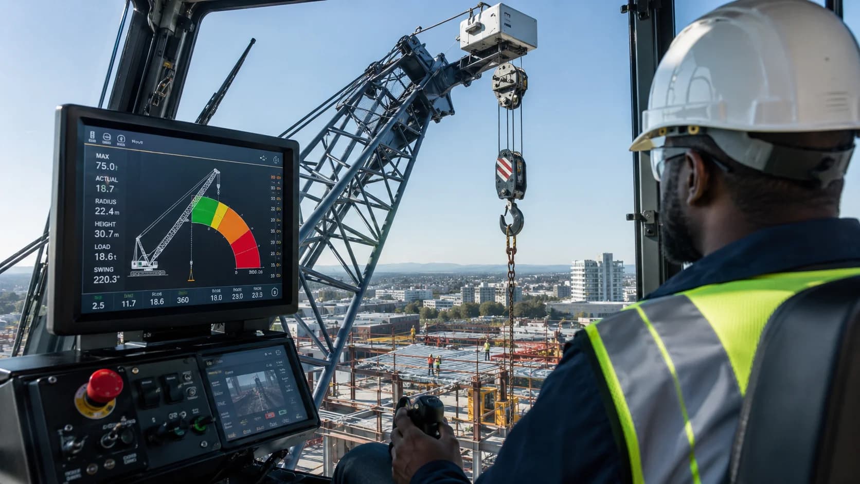
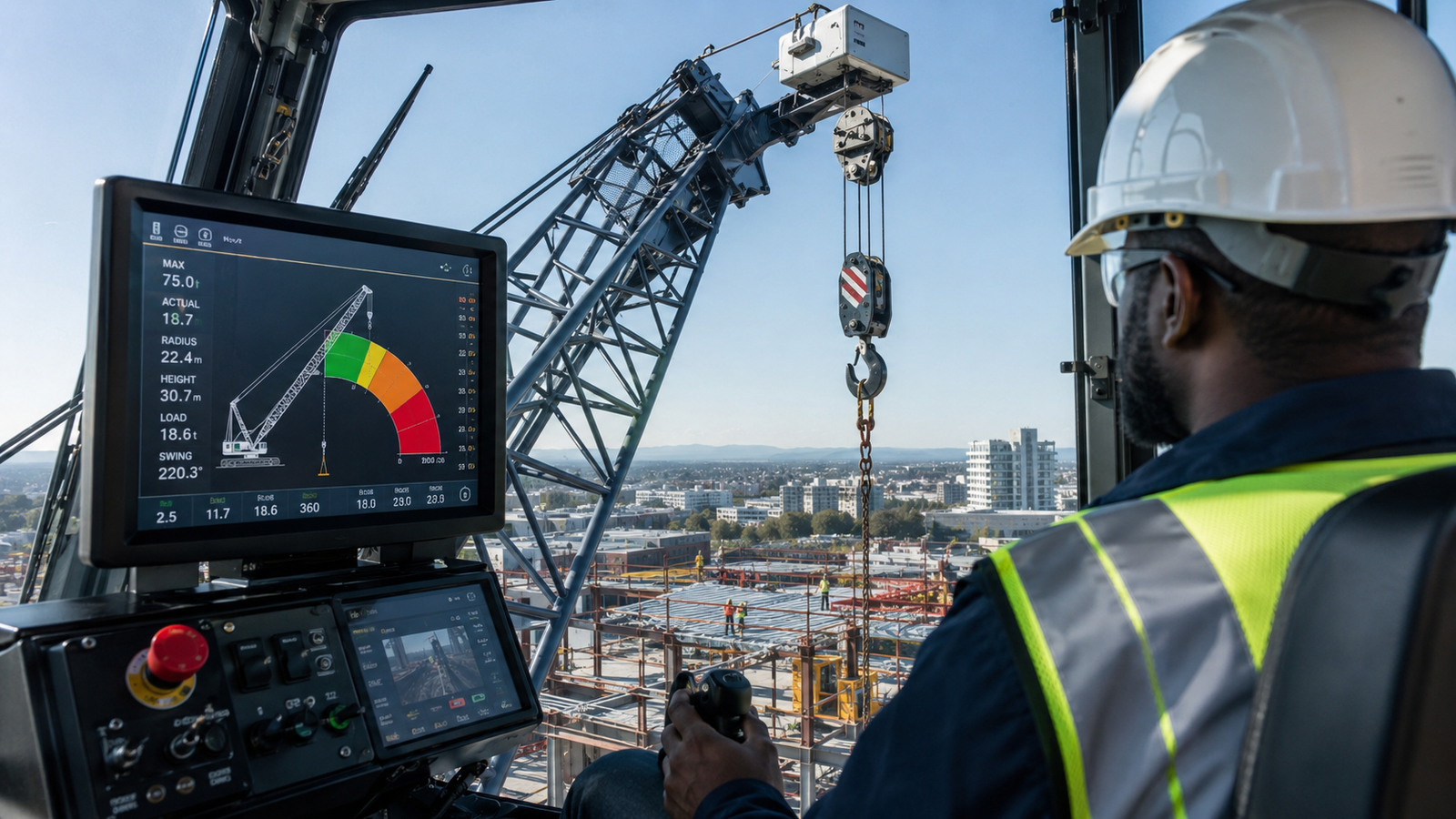
Modern cranes use electronic and mechanical safety systems to help operators understand load condition and prevent damaging hook-block contact. Two of the most important are the load moment indicator, often called an LMI or rated-capacity indicator, and the anti-two-block system, commonly abbreviated A2B. The LMI estimates or measures parameters such as boom length, boom angle, radius, crane configuration, and load to compare current operating condition with the crane’s rated-capacity information. An anti-two-block device detects when the hook block or overhaul ball approaches the boom tip and can warn the operator or interrupt selected functions. These systems are valuable, but they are aids—not substitutes for a load chart, correct setup, inspection, and trained operation. This guide explains what each system does, how the sensors work at a practical level, what the displays mean, common failure modes, pre-operation checks, and why correct configuration input is essential.
Use this guide with the exact manufacturer documentation. Capacities, configuration limits, inspection criteria, and operating procedures vary by crane model and jurisdiction.
What a Load Moment Indicator Monitors
An LMI uses crane geometry and load-related information to estimate how close the crane is operating to a rated-capacity limit for the selected configuration. Confirm this point against the exact crane data and the actual field condition before proceeding.
Typical inputs can include boom length, boom angle, radius, counterweight, outrigger position, jib condition, reeving, and measured load or hydraulic pressure, depending on the crane design. Confirm this point against the exact crane data and the actual field condition before proceeding.
The display may show actual load, allowable load, percentage utilization, radius, boom length, boom angle, warnings, and configuration information so the operator can see how the lift is developing. Confirm this point against the exact crane data and the actual field condition before proceeding.
Because the system depends on accurate sensors and correct setup data, an incorrect configuration selection can produce misleading capacity information even when the electronics are functioning normally. Confirm this point against the exact crane data and the actual field condition before proceeding.
The LMI should be treated as a cross-check against a properly planned lift, not as permission to explore the edge of the crane envelope until an alarm activates. Confirm this point against the exact crane data and the actual field condition before proceeding.
On a congested project, the limiting condition may occur later in the swing or at the set point, so check the complete lift envelope before mobilization.
How Load Moment Relates to Radius
Load moment is closely related to load multiplied by horizontal radius, so a lighter load at a long radius can create a similar or greater overturning demand than a heavier load close to the crane. Confirm this point against the exact crane data and the actual field condition before proceeding.
As the operator booms down or extends the telescope, radius can increase and the allowable capacity can fall even though the suspended load weight does not change. Confirm this point against the exact crane data and the actual field condition before proceeding.
The LMI tracks these geometry changes and typically provides increasing warning as utilization approaches a programmed limit based on the crane configuration. Confirm this point against the exact crane data and the actual field condition before proceeding.
Dynamic motion, side loading, ground failure, wind, and other hazards are not fully represented by a simple moment value, which is one reason the system cannot replace operator judgment and lift planning. Confirm this point against the exact crane data and the actual field condition before proceeding.
Operators should understand which displayed values are measured, which are calculated, and which depend on configuration entries so they can recognize readings that do not match physical reality. Confirm this point against the exact crane data and the actual field condition before proceeding.
Marking the crane center, support locations, load path, and landing area before setup makes the assumptions visible to the entire lifting team.
Understanding Anti-Two-Block Protection
Two-blocking occurs when the hook block, overhaul ball, or other lower load-handling component contacts the boom-tip sheaves or upper block while the hoist line is still being tensioned. Confirm this point against the exact crane data and the actual field condition before proceeding.
The resulting force can damage wire rope, sheaves, boom-tip components, hooks, or attachments and can lead to dropped loads or structural damage. Confirm this point against the exact crane data and the actual field condition before proceeding.
An anti-two-block device commonly uses a switch, weight, cable, proximity sensor, or another arrangement that detects the approaching block and activates an alarm or motion cutout. Confirm this point against the exact crane data and the actual field condition before proceeding.
Depending on the crane design, the system may stop hoist-up, boom-down, telescope-out, or other functions that could worsen the two-block condition while allowing motion that relieves it. Confirm this point against the exact crane data and the actual field condition before proceeding.
The exact response varies by crane, so operators should test and understand the installed system rather than assuming every A2B behaves the same way. Confirm this point against the exact crane data and the actual field condition before proceeding.
When uncertainty remains, conservative planning is more reliable than using every unit of theoretical capacity. Keep usable margin for normal variation in weight, radius, and positioning.
Pre-Operation Functional Checks
The operator should verify that the LMI powers up correctly, shows the expected crane configuration, and displays reasonable boom length, angle, radius, and load information before relying on it. Confirm this point against the exact crane data and the actual field condition before proceeding.
Outrigger position, counterweight, jib installation, reeving, and other selectable inputs should be compared with the physical crane rather than copied from a previous shift. Confirm this point against the exact crane data and the actual field condition before proceeding.
The anti-two-block function should be tested according to the manufacturer procedure, confirming both warning and motion-limiting behavior where applicable. Confirm this point against the exact crane data and the actual field condition before proceeding.
Damaged cables, loose sensors, bent switches, missing A2B weights, contaminated connectors, and boom repairs can affect system performance and should be reported for correction. Confirm this point against the exact crane data and the actual field condition before proceeding.
A fault code, bypass indicator, unexplained value, or failed test is not something to work around casually; the crane should be handled according to the manufacturer and site safety procedure. Confirm this point against the exact crane data and the actual field condition before proceeding.
After weather changes, relocation, or a configuration change, reconfirm the condition that controls the lift instead of assuming the earlier setup is still valid.
Common Misunderstandings and Failure Modes
One common mistake is assuming the LMI knows the entire jobsite; it does not automatically account for soft ground, underground voids, nearby power lines, poor rigging, wind effects, or an incorrectly identified load. Confirm this point against the exact crane data and the actual field condition before proceeding.
Another error is entering the wrong outrigger or jib configuration, which can make the system compare the lift against the wrong capacity information. Confirm this point against the exact crane data and the actual field condition before proceeding.
Sensors can drift, become damaged, or lose calibration, and wiring faults can create intermittent readings that may only appear at certain boom lengths or slew positions. Confirm this point against the exact crane data and the actual field condition before proceeding.
A2B devices can be defeated by missing weights, damaged cables, frozen mechanisms, improper installation after boom changes, or intentional bypassing, all of which remove an important protective layer. Confirm this point against the exact crane data and the actual field condition before proceeding.
Good troubleshooting starts by stopping the operation, comparing the display with actual crane geometry, reviewing fault information, and involving qualified service personnel rather than guessing. Confirm this point against the exact crane data and the actual field condition before proceeding.
A short handover record of configuration, key dimensions, support assumptions, rigging, and restrictions helps prevent the next shift from using an outdated plan.
Using Safety Systems Without Becoming Dependent on Them
The lift should be planned from the manufacturer chart before operation, including the load, rigging, radius, boom length, deductions, setup condition, and expected capacity margin. Confirm this point against the exact crane data and the actual field condition before proceeding.
During the lift, the LMI can confirm that measured crane geometry follows the plan and can alert the operator when changing radius or configuration moves the crane toward a limit. Confirm this point against the exact crane data and the actual field condition before proceeding.
The operator should still watch load behavior, ground conditions, boom deflection, wind, obstructions, and communication with the signal person because many hazards exist outside the electronic system. Confirm this point against the exact crane data and the actual field condition before proceeding.
A2B protection reduces the risk of hook-block contact, but the operator should maintain visual and procedural awareness of hook height, especially when telescoping or booming down near the tip. Confirm this point against the exact crane data and the actual field condition before proceeding.
The strongest safety approach combines planning, inspection, trained people, reliable instrumentation, conservative operation, and an immediate stop when the system or the physical crane does not behave as expected. Confirm this point against the exact crane data and the actual field condition before proceeding.
For example, a lift can change when the crane must be positioned farther away than planned. Recalculate the working condition rather than treating the extra radius as insignificant.
Field Planning Checklist
Before the lift begins, convert the planning discussion into a short field checklist. A checklist does not replace judgment; it makes sure the agreed assumptions are visible and repeatable. The following items should be adapted to the exact crane, manufacturer instructions, project lift plan, and local requirements:
- Confirm LMI display powers up normally.
- Match configuration settings to the physical crane.
- Verify reasonable radius, boom length, and angle readings.
- Test anti-two-block system as specified.
- Check sensors, cables, weights, and switches.
- Review active fault or bypass indicators.
- Compare planned capacity with displayed capacity.
- Do not use alarms as a target operating point.
- Stop for unexplained or inconsistent readings.
- Use qualified service personnel for faults and calibration.
A useful completion rule is that every unchecked item must have an owner and a reason. If the crew cannot confirm a load weight, support condition, configuration setting, or communication method, that uncertainty should be resolved before the lift proceeds. This is particularly important when a change appears small, because crane capacity and stability can be sensitive to geometry and support conditions.
Common Planning Mistakes to Avoid
- Using a crane’s advertised maximum capacity as though it applies at every radius and boom length. The better practice is to identify the assumption during planning, assign a clear verification method, and stop when the field condition no longer matches the basis of the lift.
- Assuming site ground is adequate because trucks or smaller equipment have already driven over it. The better practice is to identify the assumption during planning, assign a clear verification method, and stop when the field condition no longer matches the basis of the lift.
- Leaving rigging, hook, attachment, counterweight, support, or configuration details until the crane is already set up. The better practice is to identify the assumption during planning, assign a clear verification method, and stop when the field condition no longer matches the basis of the lift.
- Treating alarms, limiters, or electronic displays as replacements for a planned load chart and physical inspection. The better practice is to identify the assumption during planning, assign a clear verification method, and stop when the field condition no longer matches the basis of the lift.
- Continuing after site conditions, weather, crane level, access, or load geometry changes from the approved plan. The better practice is to identify the assumption during planning, assign a clear verification method, and stop when the field condition no longer matches the basis of the lift.
Frequently Asked Questions
Does an LMI prevent every overload?
No. It is an aid based on sensors, inputs, and programmed crane data. Incorrect configuration, sensor faults, ground failure, side loading, wind, or other conditions can create risk outside what the system can prevent. Always confirm model-specific limits in the crane manual and project plan.
What does “two-block” mean?
It is contact between the lower hook block or overhaul ball and the boom-tip or upper sheave area while hoist-line tension continues. This can damage the rope and crane components. Always confirm model-specific limits in the crane manual and project plan.
Can I keep working if the anti-two-block system is bypassed?
Follow the manufacturer and applicable site or regulatory requirements. A bypass removes a protective function and should never be treated as normal operation without a specifically authorized procedure. Always confirm model-specific limits in the crane manual and project plan.
Why does the LMI capacity change when I boom down?
Booming down normally increases horizontal radius. Greater radius increases load moment and usually reduces the crane’s rated capacity for the same suspended weight. Always confirm model-specific limits in the crane manual and project plan.
What should I do if the display does not match the crane position?
Stop and verify configuration and sensor condition. Do not simply trust either the screen or a rough visual estimate; have the discrepancy resolved under the crane’s troubleshooting procedure. Always confirm model-specific limits in the crane manual and project plan.
Conclusion
Good crane work is built on disciplined preparation. The most useful habit is to keep connecting the planned lift back to measurable facts: actual load, actual radius, actual configuration, actual support condition, and actual clearance. When those facts remain inside the manufacturer limits and the crew understands the plan, the crane can be used efficiently without relying on guesswork. When one of those facts changes, the plan should change with it. Treat the load chart, setup information, rigging data, safety systems, and site conditions as one connected system, and involve qualified personnel whenever the lift is unusual, close to a limit, or affected by uncertain ground or structural conditions.
Get More Expert Guides & Updates
Subscribe for Machinery.org guide updates and product learning content.