
Verified guide word count: 3,461 words
Introduction
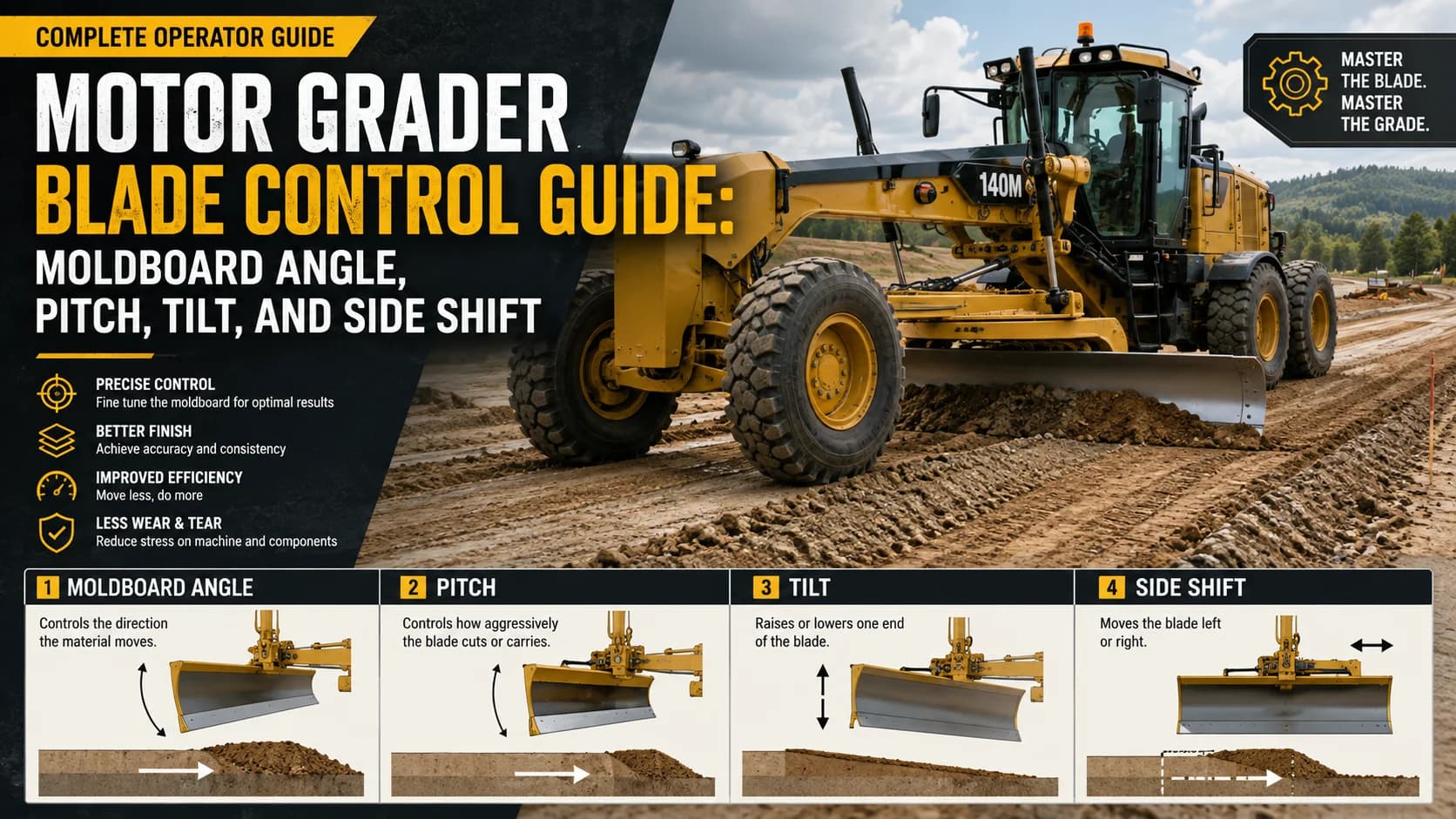
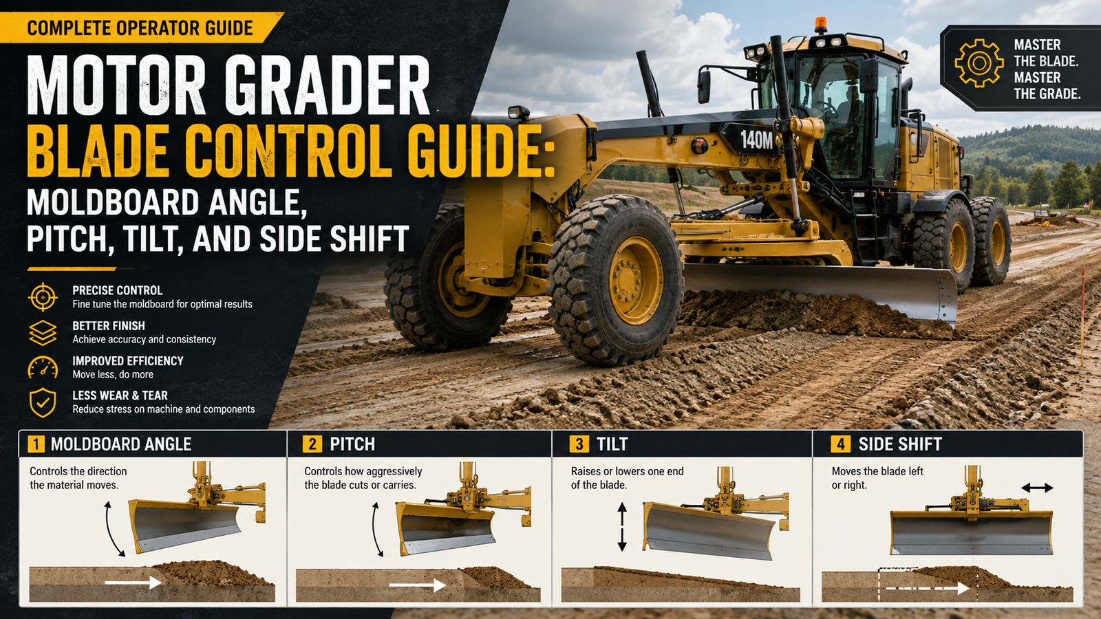
A motor grader is capable of precise shaping because the moldboard can be rotated, pitched, raised, lowered, and shifted far beyond the machine centerline.
New operators often concentrate on blade height, but the direction and quality of material flow are equally controlled by moldboard angle, pitch, end lift, side shift, wheel lean, articulation, and machine position.
The purpose of blade control is not simply to push soil or aggregate. It is to create a controlled rolling action that places material where it is needed while holding elevation and cross slope.
This guide explains the practical effect of the major blade movements and how to combine them for cutting, spreading, ditching, shoulder work, crown building, and fine grading.
Moldboard Angle
Rotating the circle changes the moldboard angle relative to the direction of travel and determines how strongly material moves from the toe toward the heel. In practice, crews should verify this condition under the actual job environment rather than relying only on a display or a previous setting. Small changes in material, temperature, wear, or machine position can change the result, so measured checks and consistent observation are important.
A useful windrowing angle allows material to roll smoothly across the curved moldboard instead of boiling in front or spilling randomly beneath the cutting edge. This point also affects productivity because the machine works best when the surrounding process is stable. When the condition begins to drift, the operator should identify the source, make one logical correction, and allow enough operating time to judge whether the correction worked.
Too much material on an angled blade increases side draft, wheel slip, steering effort, and the chance of leaving an inconsistent grade. From a quality-control perspective, the result should be checked repeatedly at planned intervals instead of only after a visible defect appears. A sequence of measurements reveals trends early and gives supervisors time to correct the process before a long section or a large volume of material is affected.
A straighter blade carries more material forward and may suit some spreading work, while a more angled blade generally increases side casting. Maintenance and operation are connected here. Wear, looseness, buildup, damaged sensors, or restricted flow can force the operator to compensate with controls, but compensation rarely produces the same consistency as restoring the component to proper condition.
Operators should watch the rolling material itself because its behavior shows whether blade angle, load, and travel speed are working together. The safest and most efficient approach is to include this item in the pre-shift plan and to define who is responsible for checking it during production. Clear communication between the main machine operator, ground crew, trucks, quality personnel, and support equipment reduces delays and prevents conflicting adjustments.
For a motor grader blade crew, the practical objective in this area is repeatability. Record the starting condition, observe how the machine and material respond, and use measured results to decide whether another adjustment is necessary. This disciplined method reduces rework, makes troubleshooting faster, and produces a process that can be repeated by the next shift.
Blade Pitch
Pitch changes the top-to-bottom attitude of the moldboard and therefore changes how aggressively the cutting edge enters the material. Experienced crews treat this as one variable in a larger system rather than an isolated setting. If performance changes, they compare material condition, machine speed, mechanical condition, and downstream capacity before assuming that one control must be adjusted.
A more aggressive cutting position can improve penetration in hard material but increases resistance, side draft, and the risk of chatter or wheel spin. In practice, crews should verify this condition under the actual job environment rather than relying only on a display or a previous setting. Small changes in material, temperature, wear, or machine position can change the result, so measured checks and consistent observation are important.
A more carrying-oriented position encourages material to climb and roll on the moldboard, which is useful during spreading and finishing. This point also affects productivity because the machine works best when the surrounding process is stable. When the condition begins to drift, the operator should identify the source, make one logical correction, and allow enough operating time to judge whether the correction worked.
Cutting-edge wear changes the effective pitch and can make a familiar control position behave differently as the edge becomes rounded or thin. From a quality-control perspective, the result should be checked repeatedly at planned intervals instead of only after a visible defect appears. A sequence of measurements reveals trends early and gives supervisors time to correct the process before a long section or a large volume of material is affected.
Operators should use enough pitch to perform the task without maintaining an unnecessarily aggressive cutting attitude throughout the entire pass. Maintenance and operation are connected here. Wear, looseness, buildup, damaged sensors, or restricted flow can force the operator to compensate with controls, but compensation rarely produces the same consistency as restoring the component to proper condition.
For a motor grader blade crew, the practical objective in this area is repeatability. Record the starting condition, observe how the machine and material respond, and use measured results to decide whether another adjustment is necessary. This disciplined method reduces rework, makes troubleshooting faster, and produces a process that can be repeated by the next shift.
Blade Tilt and End Lift
Raising one end of the moldboard relative to the other creates a transverse cutting plane used for crown, shoulder slope, ditch slope, and transitions. The safest and most efficient approach is to include this item in the pre-shift plan and to define who is responsible for checking it during production. Clear communication between the main machine operator, ground crew, trucks, quality personnel, and support equipment reduces delays and prevents conflicting adjustments.
The final cross slope is influenced not only by the blade but also by machine roll, tire position, articulation, wheel lean, and the amount of material carried. Experienced crews treat this as one variable in a larger system rather than an isolated setting. If performance changes, they compare material condition, machine speed, mechanical condition, and downstream capacity before assuming that one control must be adjusted.
Large end-lift corrections while the blade is heavily loaded can leave steps or ridges because the cutting edge changes elevation before the material flow stabilizes. In practice, crews should verify this condition under the actual job environment rather than relying only on a display or a previous setting. Small changes in material, temperature, wear, or machine position can change the result, so measured checks and consistent observation are important.
Automatic cross-slope systems can reduce operator workload but should be checked against an independent measurement and a properly calibrated zero point. This point also affects productivity because the machine works best when the surrounding process is stable. When the condition begins to drift, the operator should identify the source, make one logical correction, and allow enough operating time to judge whether the correction worked.
Operators should make slope changes gradually so the finished surface transitions smoothly instead of showing an abrupt break. From a quality-control perspective, the result should be checked repeatedly at planned intervals instead of only after a visible defect appears. A sequence of measurements reveals trends early and gives supervisors time to correct the process before a long section or a large volume of material is affected.
For a motor grader blade crew, the practical objective in this area is repeatability. Record the starting condition, observe how the machine and material respond, and use measured results to decide whether another adjustment is necessary. This disciplined method reduces rework, makes troubleshooting faster, and produces a process that can be repeated by the next shift.
Side Shift and Reach
Side shift moves the moldboard laterally so the toe or heel can work outside the normal tire path for shoulder, ditch, bank, and edge work. Maintenance and operation are connected here. Wear, looseness, buildup, damaged sensors, or restricted flow can force the operator to compensate with controls, but compensation rarely produces the same consistency as restoring the component to proper condition.
As the blade moves farther from the machine centerline, leverage and side draft increase, so the operator should reduce load and pay close attention to tire support. The safest and most efficient approach is to include this item in the pre-shift plan and to define who is responsible for checking it during production. Clear communication between the main machine operator, ground crew, trucks, quality personnel, and support equipment reduces delays and prevents conflicting adjustments.
Articulation and front-wheel lean can help counteract side forces, but they should not be used to compensate for an overloaded moldboard. Experienced crews treat this as one variable in a larger system rather than an isolated setting. If performance changes, they compare material condition, machine speed, mechanical condition, and downstream capacity before assuming that one control must be adjusted.
Extreme side shift changes visibility and increases the importance of checking for workers, utilities, rocks, drop-offs, and other obstacles outside the normal wheel path. In practice, crews should verify this condition under the actual job environment rather than relying only on a display or a previous setting. Small changes in material, temperature, wear, or machine position can change the result, so measured checks and consistent observation are important.
Side shift is most effective when used as part of a complete blade geometry rather than as a simple reach control. This point also affects productivity because the machine works best when the surrounding process is stable. When the condition begins to drift, the operator should identify the source, make one logical correction, and allow enough operating time to judge whether the correction worked.
For a motor grader blade crew, the practical objective in this area is repeatability. Record the starting condition, observe how the machine and material respond, and use measured results to decide whether another adjustment is necessary. This disciplined method reduces rework, makes troubleshooting faster, and produces a process that can be repeated by the next shift.
Circle Rotation, Articulation, and Wheel Lean
Circle rotation creates the main blade angle, while articulation changes the relationship between front and rear frames and can move rear wheels away from the finished surface. From a quality-control perspective, the result should be checked repeatedly at planned intervals instead of only after a visible defect appears. A sequence of measurements reveals trends early and gives supervisors time to correct the process before a long section or a large volume of material is affected.
Front-wheel lean helps resist side draft from an angled cutting edge and can improve steering control when the blade is moving a moderate windrow. Maintenance and operation are connected here. Wear, looseness, buildup, damaged sensors, or restricted flow can force the operator to compensate with controls, but compensation rarely produces the same consistency as restoring the component to proper condition.
Excessive articulation makes machine response less intuitive and should be avoided when a simpler geometry can perform the pass. The safest and most efficient approach is to include this item in the pre-shift plan and to define who is responsible for checking it during production. Clear communication between the main machine operator, ground crew, trucks, quality personnel, and support equipment reduces delays and prevents conflicting adjustments.
Wheel lean cannot replace correct blade loading, and constant tire sliding is a sign that the cut, angle, or material volume should be reduced. Experienced crews treat this as one variable in a larger system rather than an isolated setting. If performance changes, they compare material condition, machine speed, mechanical condition, and downstream capacity before assuming that one control must be adjusted.
The most stable grading setup is one in which blade geometry, machine alignment, and available traction are balanced before fine corrections begin. In practice, crews should verify this condition under the actual job environment rather than relying only on a display or a previous setting. Small changes in material, temperature, wear, or machine position can change the result, so measured checks and consistent observation are important.
For a motor grader blade crew, the practical objective in this area is repeatability. Record the starting condition, observe how the machine and material respond, and use measured results to decide whether another adjustment is necessary. This disciplined method reduces rework, makes troubleshooting faster, and produces a process that can be repeated by the next shift.
Cutting Hard Material
Hard-packed base, dry clay, and compacted gravel should be attacked with controlled depth, suitable pitch, and, where available, scarifiers or rippers. This point also affects productivity because the machine works best when the surrounding process is stable. When the condition begins to drift, the operator should identify the source, make one logical correction, and allow enough operating time to judge whether the correction worked.
Trying to remove the full depth in one heavy moldboard pass can cause bouncing, side draft, tire spin, and unnecessary stress on the cutting edge and circle. From a quality-control perspective, the result should be checked repeatedly at planned intervals instead of only after a visible defect appears. A sequence of measurements reveals trends early and gives supervisors time to correct the process before a long section or a large volume of material is affected.
Once the hard layer is loosened, reduce cutting aggressiveness and use the moldboard to roll, mix, and relocate the material. Maintenance and operation are connected here. Wear, looseness, buildup, damaged sensors, or restricted flow can force the operator to compensate with controls, but compensation rarely produces the same consistency as restoring the component to proper condition.
A lighter final cut produces better smoothness than trying to finish with the same aggressive setup used for breakout work. The safest and most efficient approach is to include this item in the pre-shift plan and to define who is responsible for checking it during production. Clear communication between the main machine operator, ground crew, trucks, quality personnel, and support equipment reduces delays and prevents conflicting adjustments.
If the blade chatters or skips, reduce load and speed and inspect edge condition instead of responding with larger hydraulic corrections. Experienced crews treat this as one variable in a larger system rather than an isolated setting. If performance changes, they compare material condition, machine speed, mechanical condition, and downstream capacity before assuming that one control must be adjusted.
For a motor grader blade crew, the practical objective in this area is repeatability. Record the starting condition, observe how the machine and material respond, and use measured results to decide whether another adjustment is necessary. This disciplined method reduces rework, makes troubleshooting faster, and produces a process that can be repeated by the next shift.
Spreading and Fine Grading
Loose aggregate should roll along the moldboard in a controlled wave, and several thinner passes usually create a more uniform layer than one overloaded pass. In practice, crews should verify this condition under the actual job environment rather than relying only on a display or a previous setting. Small changes in material, temperature, wear, or machine position can change the result, so measured checks and consistent observation are important.
Side shift can keep the windrow away from the tires so the machine does not repeatedly drive through material that is being prepared for final grade. This point also affects productivity because the machine works best when the surrounding process is stable. When the condition begins to drift, the operator should identify the source, make one logical correction, and allow enough operating time to judge whether the correction worked.
Fine grading uses a light blade load, steady travel speed, small lift corrections, and enough angle to move excess material without creating a large windrow. From a quality-control perspective, the result should be checked repeatedly at planned intervals instead of only after a visible defect appears. A sequence of measurements reveals trends early and gives supervisors time to correct the process before a long section or a large volume of material is affected.
The operator should look well ahead of the cutting edge so steering and elevation corrections remain smooth instead of reacting to every small surface mark. Maintenance and operation are connected here. Wear, looseness, buildup, damaged sensors, or restricted flow can force the operator to compensate with controls, but compensation rarely produces the same consistency as restoring the component to proper condition.
Machine-control automation can hold elevation or slope, but the operator must still manage material because automation cannot fill a low area when no loose material is available. The safest and most efficient approach is to include this item in the pre-shift plan and to define who is responsible for checking it during production. Clear communication between the main machine operator, ground crew, trucks, quality personnel, and support equipment reduces delays and prevents conflicting adjustments.
For a motor grader blade crew, the practical objective in this area is repeatability. Record the starting condition, observe how the machine and material respond, and use measured results to decide whether another adjustment is necessary. This disciplined method reduces rework, makes troubleshooting faster, and produces a process that can be repeated by the next shift.
Maintenance, Training, and Common Errors
Circle wear strips, drawbar joints, lift-cylinder pins, side-shift guides, cutting edges, tires, steering, articulation components, and hydraulic cylinders should be kept tight and correctly adjusted. Experienced crews treat this as one variable in a larger system rather than an isolated setting. If performance changes, they compare material condition, machine speed, mechanical condition, and downstream capacity before assuming that one control must be adjusted.
Excessive play in the circle or linkage makes the blade move after the operator sets it and reduces the accuracy of fine grading. In practice, crews should verify this condition under the actual job environment rather than relying only on a display or a previous setting. Small changes in material, temperature, wear, or machine position can change the result, so measured checks and consistent observation are important.
A common operator mistake is carrying too much material and then trying to fight side draft with wheel lean, articulation, and constant steering corrections. This point also affects productivity because the machine works best when the surrounding process is stable. When the condition begins to drift, the operator should identify the source, make one logical correction, and allow enough operating time to judge whether the correction worked.
Another common mistake is moving several controls continuously instead of first choosing a stable moldboard geometry for the pass. From a quality-control perspective, the result should be checked repeatedly at planned intervals instead of only after a visible defect appears. A sequence of measurements reveals trends early and gives supervisors time to correct the process before a long section or a large volume of material is affected.
Training is most effective when operators practice one control at a time, measure the resulting slope or windrow, and then combine the motions in more complex shoulder and ditch work. Maintenance and operation are connected here. Wear, looseness, buildup, damaged sensors, or restricted flow can force the operator to compensate with controls, but compensation rarely produces the same consistency as restoring the component to proper condition.
For a motor grader blade crew, the practical objective in this area is repeatability. Record the starting condition, observe how the machine and material respond, and use measured results to decide whether another adjustment is necessary. This disciplined method reduces rework, makes troubleshooting faster, and produces a process that can be repeated by the next shift.
Field Operating Checklist
Before work begins, review the job objective, material condition, planned production rate, machine configuration, inspection requirements, traffic or site movement, and the conditions that require the motor grader blade to stop. Confirm that high-wear components, sensors, guards, warning systems, fluid levels, and support equipment are ready. During production, watch for changes in sound, vibration, material flow, machine load, surface condition, and the distance between the main machine and support equipment. Measure quality early enough to identify trends. Record major setting changes, delays, unusual material, weather changes, and maintenance issues. At the end of the shift, clean and inspect the machine according to the manufacturer’s procedure, report defects while they are fresh in memory, and compare planned production with actual production. A short end-of-shift review helps the next crew begin from known conditions rather than repeating the same troubleshooting process.
Conclusion
The motor grader blade performs best when operators understand the physical process rather than treating the controls as isolated switches. Good production comes from correct setup, stable material flow, reasonable machine speed, mechanical condition, frequent measurement, and coordinated support equipment. The machine should be operated within the manufacturer’s requirements and the project specification, with changes made deliberately and verified from the result. When these habits become routine, quality becomes more consistent, wear is easier to manage, and the crew spends less time correcting preventable defects.
Get More Expert Guides & Updates
Subscribe for Machinery.org guide updates and product learning content.